How to Replace a Lower Control Arm: Steps, Tools & Torque
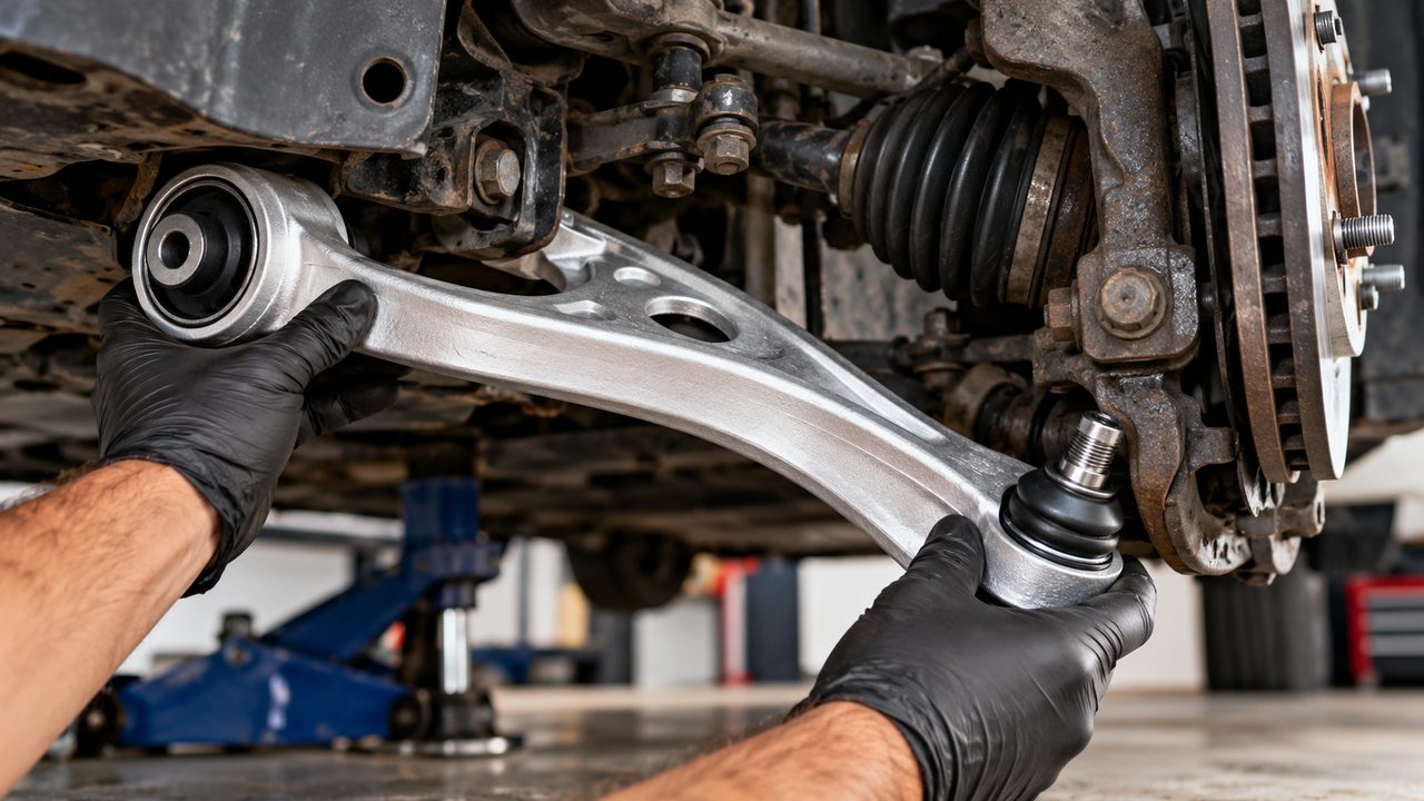
To replace a lower control arm, safely support the vehicle and suspension, disconnect the arm from the steering knuckle, remove its chassis-side pivot bolts, and fit the new assembly. The most important finishing step is tightening the control arm bushing bolts at the manufacturer’s specified suspension position—usually normal ride height—before checking the wheel alignment.
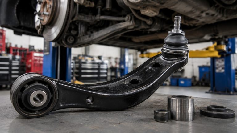
On many passenger cars, the lower control arm is replaced as a complete assembly with new bushings and a ball joint already installed. That avoids pressing individual parts into the old arm, but it doesn’t eliminate the tricky bits: seized pivot bolts, a stubborn ball joint stud, or a suspension that moves as soon as a connection is released.
Here’s the basic lower control arm replacement procedure:
- Confirm the correct lower control arm and compare the replacement assembly.
- Read the vehicle-specific procedure for controlling suspension spring loads.
- Raise and secure the vehicle, then remove the wheel and necessary access components.
- Mark any eccentric alignment bolts and note the original hardware arrangement.
- Support the steering knuckle and separate the lower ball joint connection.
- Remove the inner pivot bolts and withdraw the old control arm.
- Inspect the mounting brackets, steering knuckle, and fasteners.
- Install the new arm, starting the pivot bolts without fully tightening them.
- Reconnect the ball joint, then torque the bushing pivots at the specified suspension position.
- Reassemble, inspect the repair, and arrange a wheel alignment.
That’s the overall process. A straightforward replacement might take an experienced DIYer a couple of hours per side. A heavily corroded vehicle, a difficult spring arrangement, or bolts seized inside the bushing sleeves can turn it into a much longer job.
Safety warning: Lower control arms can be part of the suspension’s spring-load path. On some vehicles, a coil spring or torsion bar applies substantial force directly to the arm. Disconnecting the ball joint or pivot bolts without the correct support and spring-control procedure can cause sudden, violent component movement. Never assume that lifting the vehicle has removed the spring load. Follow the factory service instructions, and leave the repair to a qualified technician if you cannot control that load safely.
Before Replacing a Lower Control Arm, Check the Suspension Design
The name sounds universal, but lower control arms aren’t all arranged the same way.
A typical MacPherson-strut car has a lower arm connecting the steering knuckle to the subframe through one or more bushings. A double-wishbone suspension uses upper and lower arms, and its lower arm may also support the spring. Some vehicles have two separate lower links per wheel instead of one triangular arm.
Those differences change the order of disassembly, the equipment needed, and which components must be supported before anything comes apart.
| Suspension arrangement | What makes the job different | What to verify first |
|---|---|---|
| MacPherson strut with separate lower arm | Often a relatively accessible complete-arm replacement | Ball joint connection, pivot-bolt access, and strut/knuckle support |
| Double-wishbone suspension | Lower arm may directly carry coil spring force | Spring-load path and approved support or unloading procedure |
| Torsion-bar suspension | Lower arm may be connected to a heavily loaded torsion-bar system | Manufacturer’s torsion-bar unloading procedure |
| Multi-link front suspension | May have separate forward and rearward lower arms | Exact arm position, mounting arrangement, and correct replacement part |
| Independent rear suspension | Lower links may control camber, wheel position, or spring support | Rear suspension diagram, spring support, and alignment hardware |
Also check whether the replacement comes with the lower ball joint already installed. Some assemblies include both inner bushings and the ball joint; others are supplied without one or more of those components.
If your original arm has only worn bushings, replacing the entire assembly isn’t necessarily required. If the arm is bent, cracked, severely corroded, or has multiple worn components, a complete replacement may make more sense.
Not sure the control arm is actually responsible for the problem? Our guide to bad lower control arm symptoms explains how bushing movement, ball joint wear, and damage to the arm differ from other suspension faults. Establishing the diagnosis first can save you from replacing a perfectly good assembly.
Tools and Parts Needed for Lower Control Arm Replacement
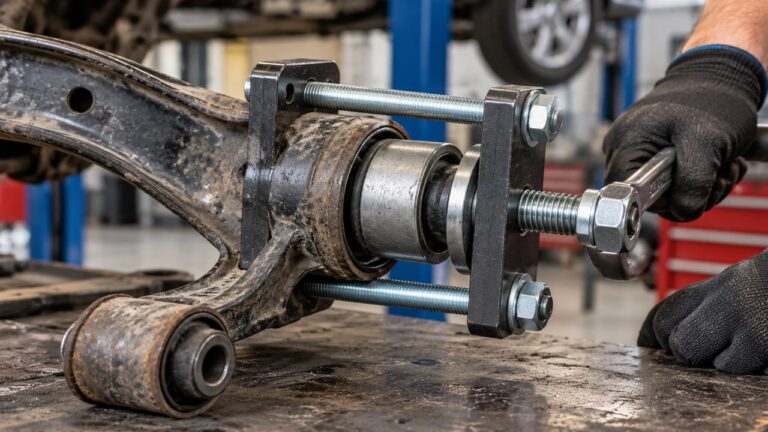
You don’t usually need a hydraulic press when installing a complete lower control arm with its bushings and ball joint already fitted. You do, however, need tools that can safely handle suspension fasteners and the ball joint connection.
For a typical front lower control arm replacement, gather:
- Correct replacement control arm: Match the year, make, model, drivetrain, suspension package, and left or right position.
- Factory repair information: Required for spring-load control, disassembly order, fastener specifications, and ride-height tightening.
- Floor jack and rated jack stands: Use only the vehicle manufacturer’s approved lifting and support locations.
- Wheel chocks: To prevent unintended movement while the vehicle is raised.
- Appropriate suspension support equipment: Depending on the design, this may include a suitable pole jack, fixtures, or approved spring-control equipment.
- Socket and combination wrench sets: Include the sizes required for pivot bolts, ball joint hardware, and any components blocking access.
- Breaker bar: Useful for loosening tight chassis fasteners.
- Torque wrench: Capable of the specified fastener torque range; a torque-angle gauge may also be needed.
- Ball joint separator: Use a tool compatible with the stud and steering knuckle connection.
- Penetrating oil and wire brush: For accessible corroded hardware.
- Paint marker: For identifying eccentric bolt positions and hardware orientation.
- Suitable pry bar: For controlled alignment of mounting points when permitted.
- New nuts, bolts, cotter pins, or other specified retainers: Some suspension fasteners must not be reused.
- Safety glasses and gloves: Particularly important when dealing with seized components.
Check the fastener requirements before starting. Some vehicles use torque-to-yield bolts or nuts that lose their intended locking characteristics after removal. Reusing them because they still look intact can be a serious mistake.
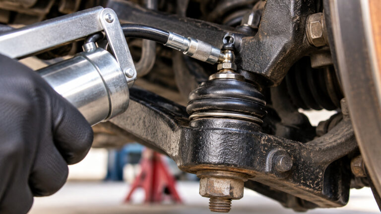
If the new arm includes a greaseable ball joint, you’ll also need the specified grease and fitting installation procedure. Most sealed joints require no additional lubrication.
One practical tip: photograph the existing arm, pivot washers, brackets, and fastener orientation before disassembly. It’s much easier to confirm where an eccentric washer belongs when you can see how it was originally installed.
How to Replace a Lower Control Arm: Step by Step
The following walkthrough covers the common operations involved in replacing a complete front lower control arm. It’s not a universal removal sequence. Suspension spring placement, axle configuration, ball joint retention, and manufacturer-specific procedures determine the exact order on your vehicle.
Step 1: Compare the New Lower Control Arm Before Disassembly
Open the replacement box and inspect the new arm before touching the car.
Compare its overall shape, bushing positions, ball joint arrangement, mounting-hole locations, and any brackets or threaded fittings. Make sure you’ve received the correct side. A left-hand control arm can look surprisingly similar to its right-hand counterpart until you try fitting it into the subframe.
If the new assembly uses hydraulic bushings, check that its orientation matches the application. These bushings may contain fluid chambers or molded voids designed to control movement in particular directions.
Inspect the ball joint boot for damage and confirm that all required retainers and mounting hardware are present.
Don’t plan to reuse the original bolts automatically. Identify which fasteners the manufacturer requires you to replace, including any torque-to-yield hardware or locking nuts.
Discovering you’ve ordered the wrong arm after disconnecting the suspension is a frustrating way to find yourself with an unusable vehicle.
Step 2: Review the Spring-Load and Support Procedure
Before lifting the car, determine how its suspension spring force is transmitted.
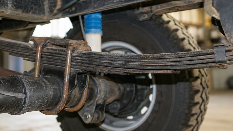
On some MacPherson-strut suspensions, the spring is retained as part of the strut assembly. On a double-wishbone or separate-coil-spring layout, the spring may sit directly on the lower control arm. A torsion bar can also apply substantial force through the arm.
These aren’t interchangeable situations.
The service manual may specify supporting a particular component, controlling or unloading the spring, or removing additional hardware before separating the arm. Follow that procedure exactly.
Do not remove the ball joint stud or inner pivot bolts while an uncontrolled spring or torsion-bar load is acting through the arm. If specialized spring fixtures or torsion-bar tools are required and you don’t have them, stop rather than improvising.
Even after the suspension load has been properly controlled, the steering knuckle and nearby components may need independent support to prevent them from dropping or swinging.
Step 3: Raise the Vehicle and Remove the Wheel
Park on level, solid ground. Apply the parking brake, place suitable wheel chocks, and loosen the wheel fasteners slightly while the tire is still supporting the vehicle.
Lift the vehicle at an approved jacking point and secure it on correctly positioned, adequately rated jack stands. Never work under a vehicle supported only by a floor jack.
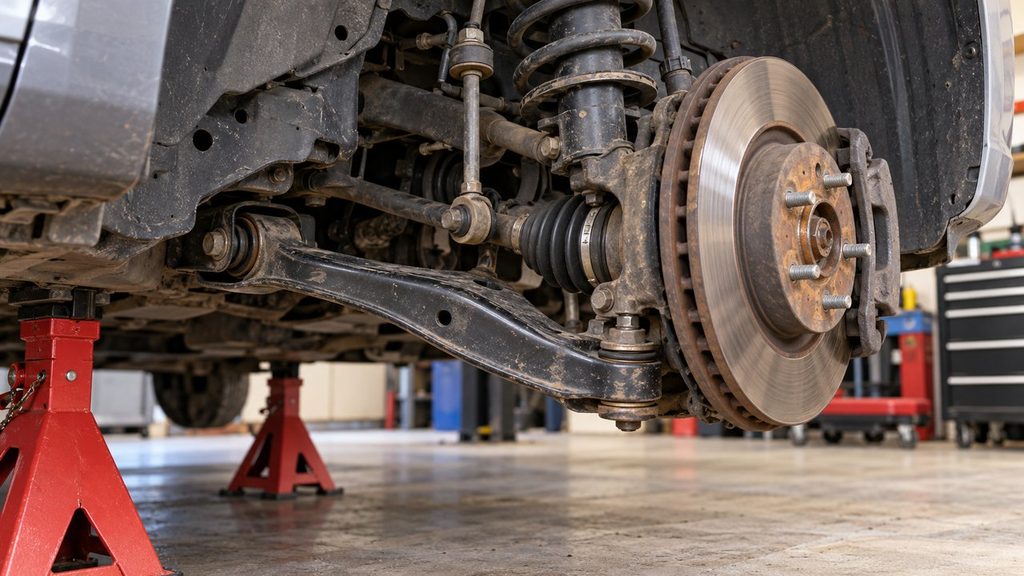
Remove the wheel and inspect the area around the lower control arm.
Find the inner pivot bolts where the bushings attach to the subframe or chassis. Then identify the outer connection between the arm and steering knuckle.
Look for components that may obstruct the repair, including the sway bar link, underbody shield, steering linkage, brake hose brackets, or lower shock mounting point.
Don’t disconnect everything in sight. The less surrounding hardware you disturb unnecessarily, the fewer opportunities you create for alignment changes, damaged wiring, or seized fasteners.
Step 4: Record Alignment Hardware and Clear the Working Area
Some lower control arms use eccentric pivot bolts or cam washers to adjust camber or caster. These components may look like ordinary mounting hardware until you notice their offset washers.
If the service procedure permits marking the original cam positions, use a paint marker to record their relationship to the bracket before removal. Photograph the arrangement as well.
Those marks can help you reassemble the vehicle close to its previous setting, but they do not replace a wheel alignment. New bushings, manufacturing tolerances, and changes in the arm’s position can alter the final geometry.
Next, disconnect only the components required to access and remove the arm.
If the sway bar end link attaches directly to the lower control arm, it may need to be disconnected. Be aware that the sway bar can carry torsional load when the suspension on one side sits at a different height. Our sway bar link removal and replacement guide covers the common stud-holding tools and problems with seized mounting nuts.
Support any brake caliper or steering-knuckle assembly that could otherwise hang from a brake hose, ABS wire, or CV axle after the control arm is disconnected.
On some vehicles, a pivot bolt cannot be withdrawn without moving an engine mount, lowering a subframe component, or following a model-specific clearance procedure. Check that requirement before trying to force the bolt through an obstruction.
Step 5: Disconnect the Lower Ball Joint From the Steering Knuckle
Once the suspension and steering knuckle are supported exactly as required, release the lower ball joint connection.
This connection doesn’t look the same on every vehicle.
On a tapered-stud design, the ball joint stud fits tightly into a matching tapered bore in the steering knuckle. It may be retained by a castle nut and cotter pin or by a locking nut.
Remove the specified retaining hardware and use a correctly fitted ball joint separator to release the tapered connection. Follow the service procedure for managing the joint as it separates.
Other vehicles use a pinch-bolt connection, where a clamp secures the ball joint stud. The retaining bolt may pass through a groove in the stud. Removing the nut alone may not allow the joint to separate; the clamp bolt and stud position must be handled as specified.
Inspect the connection before choosing a separator. A tool intended for a conventional tapered joint may be unsuitable for a pinch-bolt arrangement or an aluminum steering knuckle.
If you’re unfamiliar with the different stud arrangements, our guide to replacing ball joints
Don’t strike the ball joint stud directly with a hammer, and don’t let the disconnected steering knuckle hang on the brake hose or axle shaft.
If the stud is stuck, stop and investigate the retaining method and tool alignment before applying more force. A damaged knuckle can make the control arm repair far more expensive.
Step 6: Remove the Inner Pivot Bolts and Old Control Arm
With the outer connection released and the suspension properly supported, move to the chassis-side mounts.
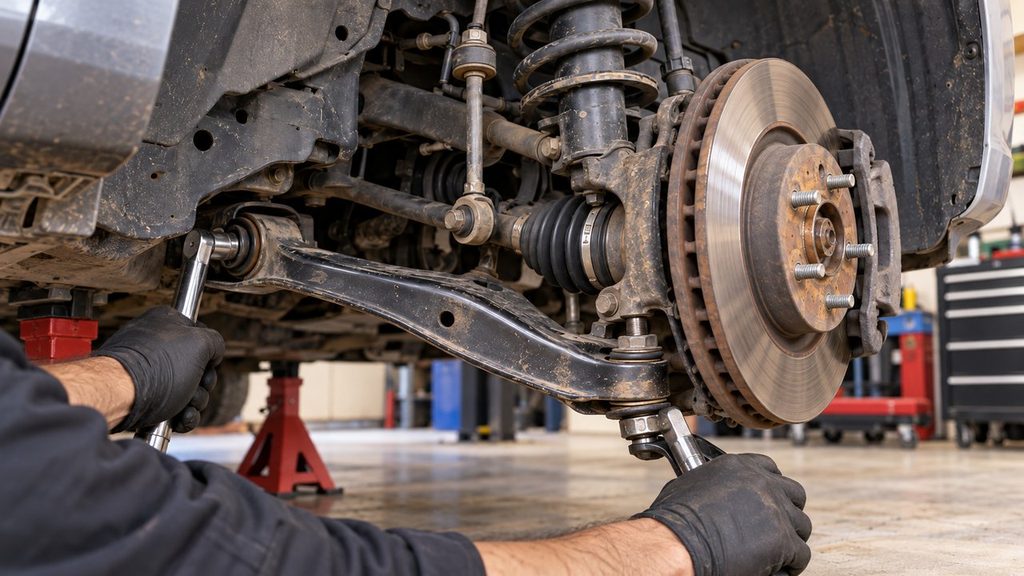
Most conventional lower control arms have one or two inner bushings secured by large pivot bolts. The bolts may run horizontally through the subframe or vertically through mounting brackets.
Use appropriately sized tools to loosen the pivot hardware. Pay attention to the original bolt direction, washer placement, eccentric cams, and any mounting spacers.
Support the arm as the final mounting fasteners are removed. Depending on its size and surrounding components, it may be heavier or more awkward to handle than expected.
Withdraw the old arm through the approved clearance path. Sometimes it slips out easily once the bolts are removed. On other vehicles, the bushings fit tightly between subframe brackets and need careful positioning.
A suitable pry bar may help position an unloaded assembly, but don’t bend the subframe brackets apart to make room. Damaged mounting ears can prevent the new arm from being securely clamped.
If a pivot bolt refuses to come out even after its nut has been removed, check whether the bolt has corroded to the bushing’s inner metal sleeve. That’s a different problem from a tight bolt head and requires a different approach.
Step 7: Inspect the Subframe and Mounting Points
Before fitting the new arm, take a close look at what the old one left behind.
Inspect the subframe brackets for cracking, heavy corrosion, distorted mounting holes, or signs that a loose pivot bolt has been moving against the metal.
Check the steering knuckle’s ball joint connection too. A tapered bore must retain the new stud correctly. A pinch-bolt arrangement needs undamaged clamping surfaces and the correct stud depth.
Clean away ordinary dirt and loose corrosion as permitted by the service information, but don’t enlarge mounting holes or grind structural material to make the replacement fit.
Compare the old and new arms side by side. This is the final chance to spot a difference in bushing width, arm geometry, ball joint stud, or mounting position.
If the old control arm is visibly bent, inspect the nearby steering knuckle, strut, subframe, and wheel for impact damage. Replacing a bent arm alone may not restore the correct geometry if another mounting point has moved.
Step 8: Position and Install the New Lower Control Arm
Guide the new arm into the subframe or chassis mounting brackets, following the specified installation direction.
Start the inner pivot bolts by hand, using the correct new hardware where required. The bolts should pass through the mounting sleeves and brackets without being forced through an obviously misaligned hole.
If necessary, adjust the arm’s supported position to align the mounting holes. Don’t use the pivot bolt as a lever to bend the bracket into place.
For conventional bonded-rubber bushings, leave the pivots at the manufacturer’s specified preliminary tightness rather than applying final torque with the suspension hanging, unless your vehicle’s instructions explicitly say otherwise.
Next, reconnect the ball joint stud to the steering knuckle.
Make sure the stud is fully seated in the correct position and the rubber dust boot isn’t trapped, pinched, or twisted.
Install the specified retaining nut or pinch bolt and tighten it according to the service instructions. On castle-nut designs, use a new cotter pin and follow the specified method for aligning the nut slot with the stud hole. Never loosen a correctly torqued castle nut just to make the holes line up.
If the replacement ball joint has an internal hex or other stud-holding feature, use it as directed during tightening. Don’t substitute a guessed torque value from another vehicle.
Reattach the sway bar link and any brackets or components removed for access, following the manufacturer’s required sequence.
Step 9: Tighten the Control Arm Bolts at the Correct Ride Height
This is one of the most important parts of the entire repair, and it’s easy to get wrong.
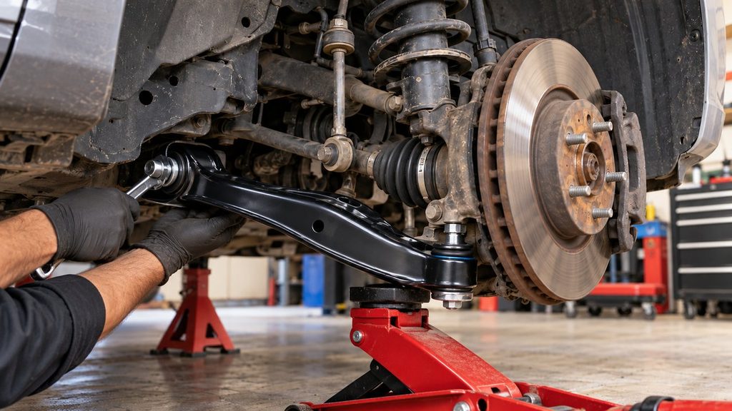
Many factory lower control arms use rubber bushings bonded to metal sleeves. When the pivot bolts are tightened, the inner sleeves become fixed in position. As the suspension travels, the rubber twists between the inner sleeves and the surrounding bushing housings.
If you fully tighten those bolts while the suspension hangs at maximum droop, the rubber may already be under significant twist when the vehicle returns to normal ride height.
That unwanted preload can shorten bushing life and cause premature cracking or separation. In some cases, it can also contribute to abnormal suspension movement or ride behavior.
For designs requiring ride-height tightening, position the suspension at the specified normal operating height using an approved support method. Some workshops use a drive-on lift; other service procedures allow the relevant suspension components to be supported at a measured position while the vehicle remains securely lifted.
Only then tighten the pivot hardware to the required torque and any specified additional angle.
Do not crawl beneath a vehicle supported only by a jack to reach the bolts at ride height. If you cannot access and torque the hardware safely at the required position, a qualified workshop should complete that operation.
Not every bushing or suspension design follows exactly the same procedure, so the vehicle-specific instructions take priority. However, tightening bonded-rubber control arm pivots at the correct suspension position is a critical general principle.
Step 10: Reassemble, Inspect, and Check Wheel Alignment
Once the required fasteners have been tightened correctly, inspect the installation before reinstalling the wheel.
Check the ball joint retention, pivot bolts, eccentric washers, sway bar link, dust boots, brake hose routing, and ABS wiring. Make sure nothing has been stretched, trapped, or left unsupported.
Verify that the replacement control arm has adequate clearance from nearby suspension and drivetrain components throughout the movement permitted by the service procedure.
Reinstall the wheel, lower the vehicle using the approved procedure, and torque the lug nuts or bolts to specification.
Complete any remaining manufacturer-required inspections. If the repair involved disturbing adjustment cams, strut connections, subframe positioning, or other wheel-locating hardware, those settings need proper verification.
Arrange a wheel alignment after lower control arm replacement. The arm directly influences wheel positioning, and replacing it can affect camber, caster, or toe. Even carefully marked eccentric bolts do not guarantee that the final settings remain correct.
Our guide to wheel alignment after suspension replacement explains why control arm work deserves particular attention and which other repairs can change suspension geometry.
If the vehicle pulls unexpectedly, the steering wheel sits noticeably off-center, or a new clunk appears, do not assume it will settle after a few miles. Reinspect the work and correct any mechanical or alignment issue before normal driving.
What If a Lower Control Arm Bolt Is Stuck?
It’s possible to do everything right and still spend most of the job fighting one pivot bolt.
On vehicles exposed to winter road salt, moisture can enter the space between the pivot bolt and the inner metal sleeve of a control arm bushing. Over time, corrosion can effectively lock them together.
You remove the nut, turn the bolt head, and discover that the bolt still refuses to slide out. Sometimes the whole rubber bushing twists instead.
That’s a useful clue. The problem may be corrosion between the bolt and sleeve rather than a seized thread.
Before applying more force, check for obstructions along the bolt’s withdrawal path. Engine mounts, transmission brackets, exhaust components, and subframe structures can prevent a perfectly free bolt from moving far enough to come out.
Penetrating oil may help exposed corrosion, but it often has difficulty reaching the full length of a bolt seized inside a long bushing sleeve.
If the bolt or captive nut begins deforming, stop. Damaging a threaded insert inside the subframe or bending a mounting bracket can turn a control arm replacement into a far more complicated repair.
Professional technicians may use specialized extraction equipment or controlled cutting methods when the bolt and sleeve cannot be separated. Those methods require enough clearance to avoid damaging brake lines, wiring, the subframe, and neighboring components.
Don’t use open-flame heating near rubber bushings, fuel or brake lines, protective coatings, or other heat-sensitive components as an improvised solution. When safe extraction isn’t possible with the available equipment, professional removal is the better choice.
Lower Control Arm Torque: What Needs to Be Tightened and When?
The word torque appears in nearly every lower control arm tutorial, but there isn’t a single number you can safely use for every car.
The pivot bolts, ball joint stud, sway bar link hardware, and wheel fasteners serve different purposes and may require completely different tightening values. Some fasteners also have a torque-plus-angle specification.
Use this table as an installation checklist, not a substitute for factory torque data.
| Fastener | Main requirement | Common mistake |
|---|---|---|
| Inner control arm pivot bolts | Specified torque or torque-angle at the required suspension position | Fully tightening bonded-rubber pivots at full droop |
| Lower ball joint retaining nut | Correct stud seating, fastener type, torque, and locking method | Guessing torque or reusing a specified single-use nut |
| Ball joint pinch bolt | Correct stud insertion depth and specified clamp hardware | Installing the bolt with the stud improperly seated |
| Eccentric alignment bolts | Correct cam arrangement, tightening procedure, and subsequent alignment | Assuming paint marks replace alignment measurements |
| Sway bar link hardware | Part- and vehicle-specific tightening requirements | Damaging the stud holding feature or overtightening rubber bushings |
| Wheel fasteners | Specified torque and tightening pattern | Relying only on an impact wrench for final tightening |
One more detail deserves attention: a replacement arm supplied with its own ball joint or mounting hardware may include updated installation instructions. Compare those instructions with the vehicle manufacturer’s procedure and resolve any differences before tightening.
Never substitute a torque figure taken from a different model year simply because its suspension looks similar. Changes in bolt diameter, thread design, knuckle material, and fastener specification can make that number inappropriate.
Can You Replace a Lower Control Arm Without Replacing the Ball Joint?
It depends on how the control arm and ball joint are supplied and which components are actually worn.
Many complete lower control arm assemblies include a new ball joint already installed. In that case, fitting the complete assembly naturally replaces the old joint as part of the repair.
Other applications use a ball joint mounted separately to the steering knuckle or control arm. Depending on the design, it may be possible to retain a serviceable joint while replacing the arm.
But don’t assume an existing ball joint is sound just because it hasn’t made noise. Inspect it using the correct manufacturer-specified procedure before deciding whether to reuse it.
If the original arm is straight, structurally sound, and its bushings are healthy, replacing only a separately serviceable worn ball joint may also be reasonable. That’s a different repair from replacing the complete lower control arm.
The sensible choice depends on the condition of the components, the available replacement assemblies, and the labor involved—not on the assumption that more new parts always make a better repair.
How Long Does It Take to Replace a Lower Control Arm?
On a relatively accessible passenger car with cooperative hardware, replacing one complete front lower control arm may take approximately 1.5 to 3 hours for someone familiar with the work. That is a planning estimate, not a guaranteed repair time.
A first-time DIY mechanic should allow additional time to identify the mounting arrangement, confirm the support procedure, handle unexpected fasteners, and check the finished installation.
Several factors can make the job substantially longer:
- Pivot bolts seized inside old bushing sleeves.
- Ball joint studs corroded into the steering knuckle.
- Suspension designs requiring specialized spring or torsion-bar equipment.
- Engine or transmission mounts blocking pivot-bolt removal.
- Subframe components that must be repositioned according to a specific procedure.
- Damaged alignment cams or mounting brackets.
- Additional disassembly around CV axles, brake components, or underbody structures.
If a vehicle uses two lower links at each front wheel, don’t assume the labor time for one triangular-arm replacement applies to the whole corner.
And remember to account for the alignment appointment. The repair isn’t truly complete until the mechanical installation has been verified and the wheel geometry checked.
Should You Replace Both Lower Control Arms at the Same Time?
Not necessarily. A damaged or worn lower control arm doesn’t automatically mean its counterpart on the opposite side is also due for replacement.
However, both arms generally experience similar mileage and road conditions. If one set of bushings has failed through normal wear, checking the other side is sensible.
Replacing both sides may also be practical when the arms are equally worn or when the repair involves significant labor to access both assemblies.
On the other hand, if one control arm was bent by a pothole or curb impact and the opposite arm remains sound, there may be no reason to replace an otherwise healthy component.
For the budget side of that decision, our lower control arm replacement cost guide covers parts, labor, and the differences between replacing one arm and both sides.
Common Lower Control Arm Replacement Mistakes
A new control arm doesn’t automatically mean the suspension is safe or correctly assembled. Most avoidable problems come from the mounting hardware, suspension support, or final tightening.
These are the mistakes worth watching for:
- Ignoring spring or torsion-bar load: Disconnecting an uncontrolled loaded arm can release substantial stored energy.
- Ordering the wrong arm: Left and right parts, front and rearward lower links, and different suspension packages aren’t necessarily interchangeable.
- Forgetting eccentric bolt orientation: Alignment adjustment hardware must be installed correctly and checked afterward.
- Letting the steering knuckle hang freely: Brake hoses, ABS wiring, and CV joints may be overstretched or damaged.
- Using an unsuitable ball joint separator: The wrong tool can damage the stud, dust boot, or steering knuckle.
- Reusing single-use hardware: Torque-to-yield bolts and specified locking nuts require replacement when instructed.
- Forcing a pivot bolt through misaligned brackets: This can damage threads or distort the mounting structure.
- Fully tightening bonded-rubber bushings at full droop: The new bushings may begin their service life under excessive twist.
- Guessing torque values: Each critical connection requires the correct application-specific procedure.
- Skipping the wheel alignment: New arm geometry and disturbed mounting hardware can affect wheel positioning.
- Ignoring other impact damage: A bent steering knuckle or damaged subframe won’t be repaired by installing a new arm alone.
The most frustrating mistakes are often the ones you don’t notice during assembly. A new arm may appear to fit perfectly even though an eccentric washer is misplaced or a rubber bushing has been tightened in the wrong position.
Taking a few minutes to verify those details is easier than dismantling everything again after the first test drive.
Frequently Asked Questions
Is replacing a lower control arm a difficult job?
It can be an intermediate DIY repair on vehicles with accessible mounting bolts and a straightforward suspension design. The difficulty increases considerably when the arm carries spring or torsion-bar load, the pivot bolts are seized, or additional subframe and drivetrain components must be moved. Safe support and correct torque procedures matter more than how quickly the old bolts can be removed.
Can you replace a lower control arm yourself?
Yes, on suitable vehicles, if you have the proper tools, factory service information, and experience with suspension work. However, spring-loaded arm arrangements, damaged mounting points, and severely corroded hardware can require equipment beyond a basic home garage. If the suspension load cannot be safely controlled, professional repair is the appropriate choice.
Do you need to remove the strut to replace a lower control arm?
Not always. Many MacPherson-strut vehicles allow the lower arm to be replaced without removing the complete strut assembly. Other designs require disconnecting the lower strut mount or moving additional components for access. Follow the vehicle’s procedure, particularly where the strut, spring, and lower arm share suspension loads.
Can you replace a lower control arm without a press?
Often, yes. A complete replacement arm supplied with bushings and a ball joint already installed usually eliminates the need to press those components into the arm. You may still need a ball joint separator, specialized support equipment, or other application-specific tools to remove and install the assembly safely.
Do lower control arm bolts need to be tightened at ride height?
Many conventional bonded-rubber control arm bushings require final pivot-bolt tightening with the suspension at its specified normal ride position. Tightening them at full droop can preload the rubber and shorten its service life. The exact tightening position and torque procedure must follow the vehicle and replacement-part manufacturer’s instructions.
Does replacing a lower control arm affect alignment?
Yes, it can. A lower control arm helps determine the wheel’s position, and replacing it may affect camber, caster, or toe. Vehicles with eccentric adjustment bolts are particularly sensitive to mounting changes. A professional alignment check is recommended after the replacement, even if the original bolt positions were marked.
What if the lower control arm ball joint won’t come out?
First verify the joint’s retaining arrangement and confirm that the suspension is safely supported. Tapered studs, pinch-bolt connections, and specialty designs require different removal methods. A suitable separator may release a seized tapered stud, but forcing the wrong tool can damage the steering knuckle. Severe corrosion may require professional equipment.
Do replacement lower control arms come with bushings?
Many complete control arm assemblies include new inner bushings and sometimes a preinstalled ball joint. Others are supplied as bare arms or with only certain components. Check the exact parts listing and inspect the new assembly before removing the original arm.
Can you replace a lower control arm without replacing both sides?
Yes. One lower control arm can generally be replaced independently when the other side remains in good condition and the manufacturer doesn’t require paired replacement. Inspect the opposite arm and its bushings and ball joint, but base the decision on actual wear or damage rather than mileage alone.
Can you drive immediately after replacing a lower control arm?
Only after all required fasteners have been correctly tightened, suspension support equipment removed, retaining hardware verified, and steering and suspension clearances checked. Follow the vehicle’s post-repair inspection and alignment requirements. If the steering feels abnormal, a new noise appears, or any part of the repair is uncertain, do not continue driving until it has been inspected.
Finish the Job With the Suspension in the Right Position
Replacing a lower control arm is often easier when you buy a complete assembly with its bushings and ball joint already fitted. There’s no need to disassemble the old arm or press individual components into it, and you can inspect the new part before taking the car apart.
But a complete arm doesn’t make the surrounding suspension any less important. The spring load still has to be controlled, the knuckle needs proper support, and every bolt must return to its correct location.
The detail that matters most after installation is the final pivot-bolt tightening. If the bushings are designed to be tightened at ride height, doing that with the suspension hanging can shorten the life of parts you’ve just paid to replace.
Use the correct replacement assembly, follow the specific service procedure, and have the wheel geometry checked afterward. If seized hardware, an unfamiliar spring arrangement, or a damaged mounting point takes the job beyond your equipment, a workshop is the safer option.
A properly installed lower control arm should restore the intended connection between the chassis and wheel assembly—not introduce new problems from rushed assembly or incorrect tightening.