Suspension Spring Rate Calculator

Use this suspension spring rate calculator to estimate the spring stiffness required for a target ride frequency. It calculates both wheel rate and spring rate using the sprung load at one corner, the suspension motion ratio and your chosen frequency.
The result is a theoretical baseline, not a guaranteed final setup. Calculate each corner or axle separately, then verify spring travel, shock travel, handling balance and manufacturer requirements before selecting components.
Spring Rate Calculator
Estimate a baseline spring rate from sprung corner load, desired ride frequency and suspension motion ratio.
This calculator provides a theoretical baseline. It does not account for anti-roll bars, tire stiffness, aerodynamic load, progressive springs, changing motion ratio or suspension binding.
What the Calculator Tells You
The calculator provides two related values:
- Wheel rate: The effective suspension stiffness measured at the wheel after accounting for the mass supported at that corner.
- Spring rate: The actual stiffness required at the spring after correcting the wheel rate for suspension leverage.
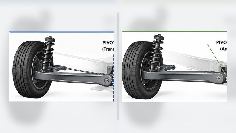
Spring rate and wheel rate are not normally equal because the spring may move a shorter distance than the wheel. A spring positioned farther inboard on a control arm usually needs a higher rate to produce the desired stiffness at the tire.
Inputs You Need
Sprung Corner Weight or Mass
Sprung mass is the portion of the vehicle supported by the springs. It includes components such as the body, chassis, engine, passengers and fuel. It excludes most of the wheels, tires, brakes, hubs and other components that move with the wheel.
For the most useful result, weigh the vehicle on four corner scales in its normal driving condition, including the driver, typical fuel load and equipment. Subtract the estimated unsprung weight at the corner being calculated.
If four-wheel scales are unavailable, dividing the relevant axle weight by two provides only an approximation. It will not account for unequal left-to-right weight distribution.
Motion Ratio
This calculator defines motion ratio as:
Motion ratio = spring travel ÷ wheel travel
If the wheel moves 1 inch and the spring compresses 0.8 inches, enter a motion ratio of 0.80.
This definition is important because some resources use the inverse ratio. Entering wheel travel divided by spring travel would produce the wrong result in this calculator.
Direct measurement near normal ride height is generally more useful than estimating the ratio from control-arm dimensions. Suspension geometry and spring angle can cause the motion ratio to change throughout wheel travel.
Target Ride Frequency
Ride frequency describes how quickly the sprung body would naturally oscillate after being displaced. It is measured in hertz, or cycles per second.
A higher target requires a higher wheel and spring rate, producing a firmer setup. A lower frequency generally provides greater compliance, although dampers, tires, bushings and suspension travel also influence how the vehicle feels.
| Vehicle Use | Broad Starting Range | General Character |
|---|---|---|
| Comfort-focused street car | 1.0–1.5 Hz | Softer and more compliant |
| Performance street or low-downforce track car | 1.5–2.5 Hz | Firmer body control |
| Dedicated racing vehicle | 2.5 Hz and above | Specialized setup requiring vehicle-specific analysis |
Do not choose a frequency solely because it sounds more “performance-oriented.” Excessive stiffness can reduce compliance and tire contact on uneven surfaces. Our guide to changing suspension stiffness safely explains the wider trade-offs.
How the Spring Rate Is Calculated
The calculator first determines the wheel rate required to achieve the selected natural frequency:
Wheel Rate = Sprung Corner Mass × (2 × π × Ride Frequency)²
For US customary units, corner weight in pounds-force is divided by gravitational acceleration—approximately 386.09 inches per second squared—to obtain compatible mass units.
The required spring rate is then calculated from the motion ratio:
Spring Rate = Wheel Rate ÷ Motion Ratio²
This relationship follows the calculator’s definition of motion ratio as spring movement divided by wheel movement. Automotive suspension manufacturers and engineering references likewise explain that wheel rate equals spring rate multiplied by the square of this ratio.
Worked Spring Rate Example
Consider one corner of a vehicle with the following values:
- Sprung corner weight: 700 lb
- Motion ratio: 0.80
- Target ride frequency: 1.50 Hz
The calculator produces an estimated wheel rate of 161.0 lb/in. Correcting that figure for the 0.80 motion ratio gives a required spring rate of approximately 251.6 lb/in.
The metric equivalents are approximately 28.2 N/mm at the wheel and 44.1 N/mm at the spring.
A commercially available spring may not match the result exactly. Select an appropriate available rate only after considering the entire suspension setup and the intended handling balance.
Spring Rate vs. Wheel Rate
| Measurement | Where It Applies | What It Represents |
|---|---|---|
| Spring rate | At the spring | Force required to compress the spring a specific distance |
| Wheel rate | At the wheel | Effective stiffness after suspension leverage |
| Ride frequency | At the sprung body | Natural oscillation rate created by wheel rate and sprung mass |
Comparing spring rates alone can be misleading. Two vehicles using identical springs may have very different wheel rates because their suspension geometries and motion ratios differ.
Calculate the Front and Rear Separately
Do not enter the total vehicle weight and treat the result as a spring recommendation for all four corners. The front and rear normally carry different loads and can have different suspension geometry.
- Measure or estimate the sprung load at one front corner.
- Use the front suspension’s motion ratio and selected front frequency.
- Repeat the calculation using the corresponding rear values.
- Repeat left and right separately when corner weights differ substantially.
Front-to-rear frequency selection influences pitch behavior as well as handling balance. It should be considered alongside anti-roll bars, alignment, damping and tire characteristics rather than treated as an isolated number.
What This Calculator Does Not Include
This is a simplified one-degree-of-freedom calculation intended to establish a starting point. It does not model:
- Tire stiffness or sidewall behavior.
- Anti-roll bar contribution during one-wheel movement.
- Aerodynamic downforce at speed.
- Progressive or dual-rate springs.
- Bump stops acting as secondary springs.
- Motion ratio changes throughout suspension travel.
- Suspension friction or binding.
- Damper compression and rebound settings.
Dampers control how quickly suspension movement settles, but they do not replace the spring-rate calculation. Learn more about this distinction in our explanation of damping and ride control.
Before Buying or Installing Springs
- Confirm the spring’s inside diameter and mounting style.
- Verify that the free length suits the available shock and suspension travel.
- Check for adequate droop without allowing the spring to become loose.
- Ensure the spring will not reach coil bind at full compression.
- Confirm that the shock will not bottom out before the intended bump stop engages.
- Recheck alignment and corner weights after changing ride height.
- Make one setup change at a time and record the result.
Suspension changes can alter steering response, braking stability and tire grip. For road vehicles, remain within legal and manufacturer requirements and use a qualified suspension specialist when the correct setup is uncertain.
Frequently Asked Questions
Can I use total vehicle weight in the calculator?
No. Use the sprung load supported by one corner. Entering total vehicle weight would produce a spring rate for the entire vehicle rather than the individual spring being selected.
What if I only know the axle weight?
Dividing axle weight by two can provide an approximate corner weight. You must then estimate and subtract the unsprung weight at that corner. Corner scales produce a more reliable result.
Why is the spring rate higher than the wheel rate?
When the spring moves less than the wheel, suspension leverage reduces its effective stiffness at the tire. The spring therefore needs a higher rate to achieve the calculated wheel rate.
Is a motion ratio of 1 always correct for a strut?
No. A strut mounted close to the wheel may have a ratio near 1, but geometry and mounting angle can still change the effective value. Measure or obtain reliable vehicle-specific data rather than assuming.
Does a higher spring rate always improve handling?
No. Excessive stiffness can reduce wheel compliance and grip on uneven roads. The correct setup balances body control, suspension travel, tire behavior and the surface on which the vehicle is used.
Does changing the shock setting change spring rate?
No. Damper settings change resistance to suspension movement, not the mechanical rate of the spring. Both components must work together, but they perform different jobs.
Use the Result as a Starting Point
The calculated spring rate provides a defensible starting point based on sprung corner load, motion ratio and target frequency. It cannot replace vehicle-specific testing or professional suspension design.
After installation, measure ride height and available travel, check alignment and evaluate the vehicle progressively in a controlled environment. If you need to adapt the setup for different surfaces, see our guide to adjusting suspension for changing road conditions.
Technical references: Penske Racing Shocks’ spring and wheel rate explanation and Racecomp Engineering’s motion-ratio guide.