How to Adjust Caster Angle on a Car or Truck
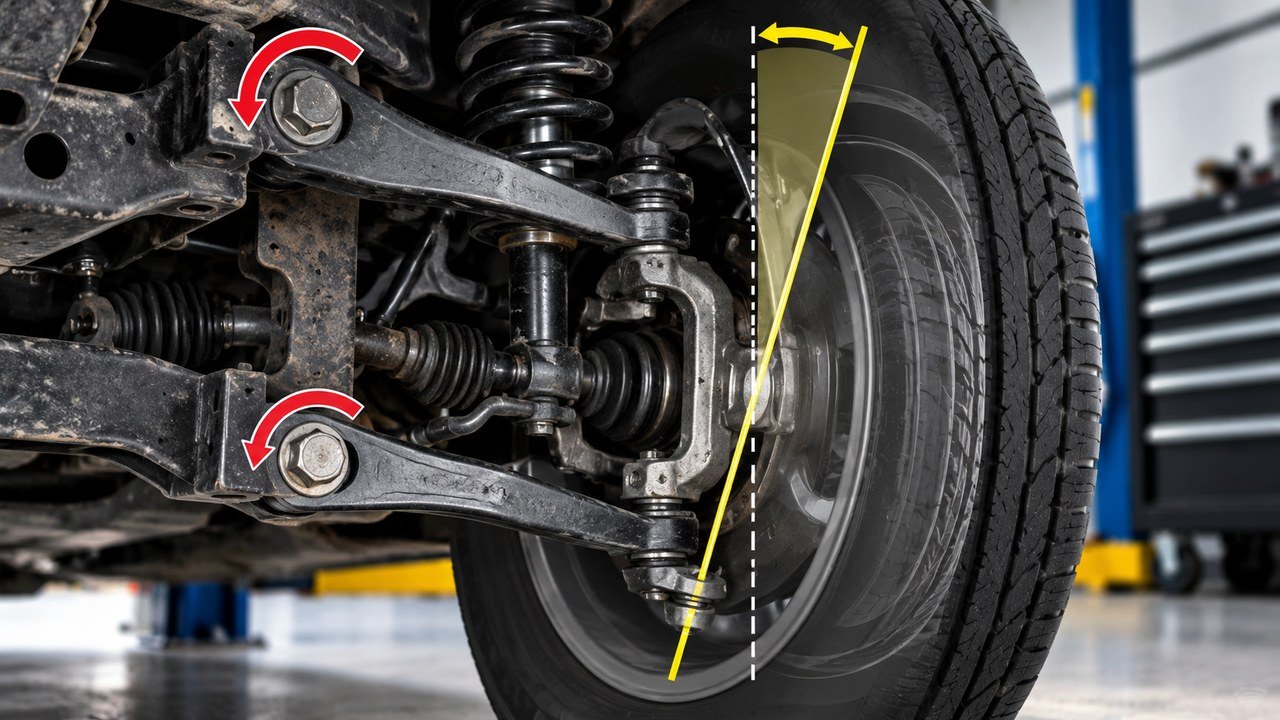
To adjust caster angle, measure the current front-wheel caster, identify the adjustment mechanism on your vehicle, and move the steering-axis pivot points forward or backward until the angle falls within the manufacturer’s specification. Depending on the suspension, that may involve eccentric control-arm bolts, alignment shims, adjustable radius arms, caster plates or aftermarket control arms. Some cars have no factory caster adjustment at all.
Here’s the important distinction: increasing positive caster generally means moving the upper steering pivot rearward relative to the lower pivot, or moving the lower pivot forward relative to the upper. How you accomplish that depends entirely on the suspension.
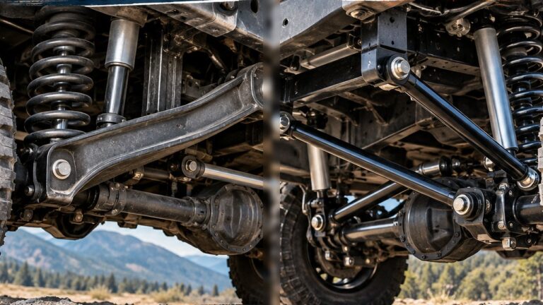
On an independent-front-suspension truck, you might turn a pair of control-arm alignment cams. On an older double-wishbone car, you might change a shim arrangement. On a lifted Jeep with a solid front axle, adjusting the control arms rotates the axle housing, which also changes the front pinion angle.
Before loosening anything, confirm that the adjustment is actually provided for your vehicle. Suspension mounting hardware is safety-critical, and the correct procedure, support method and torque specifications must come from the factory service manual or approved component instructions.
Find Your Caster Adjustment Method First
Not every car or truck has an adjustment point. In fact, trying to find a caster bolt on a suspension that was never designed with one is a good way to waste an afternoon.
Start by identifying the front suspension and checking the service information.
| Front suspension | Possible caster adjustment | Important limitation |
|---|---|---|
| Double wishbone / SLA | Control-arm eccentric cams, shims or adjustable arms | Caster and camber often interact |
| Independent front suspension (IFS) truck | Lower or upper control-arm cams, alignment kits or adjustable arms | Factory adjustment range varies by model |
| MacPherson strut | Compatible fore-aft adjustable top mounts or manufacturer-approved correction parts | Many have fixed factory caster |
| Solid front axle with control arms | Adjustable control arms, caster cams or approved bushings | Axle rotation also changes pinion angle |
| Radius-arm / strut-rod suspension | Adjustable arms, rods or specific mounting provisions | Rod geometry and bushing preload matter |
| Beam suspension with adjustable ball-joint sleeves | Vehicle-specific eccentric sleeves or bushings | Adjustment may affect both caster and camber |
This is a guide to the methods, not a claim that every suspension listed has those adjustments. Two trucks with similar-looking front ends can have completely different factory alignment provisions.
If you’re unsure what positive and negative caster mean or how caster influences steering stability, our caster angle guide covers that background. Here we’ll concentrate on the measurement and correction process.
How to Measure Caster Before Adjusting It
Caster isn’t as easy to check as camber. You can’t simply hold a digital angle finder against a stationary wheel and read the caster angle.
The steering axis is an imaginary line through the suspension’s steering pivots. To measure its inclination accurately, alignment equipment normally uses a caster sweep: the front wheels are turned through a known angle while the equipment records how camber changes.
The Caster Sweep Method
A traditional caster/camber gauge often uses a steering sweep of approximately 20 degrees to one side and 20 degrees to the other. Many modern alignment machines use a guided procedure with their own specified steering angles.
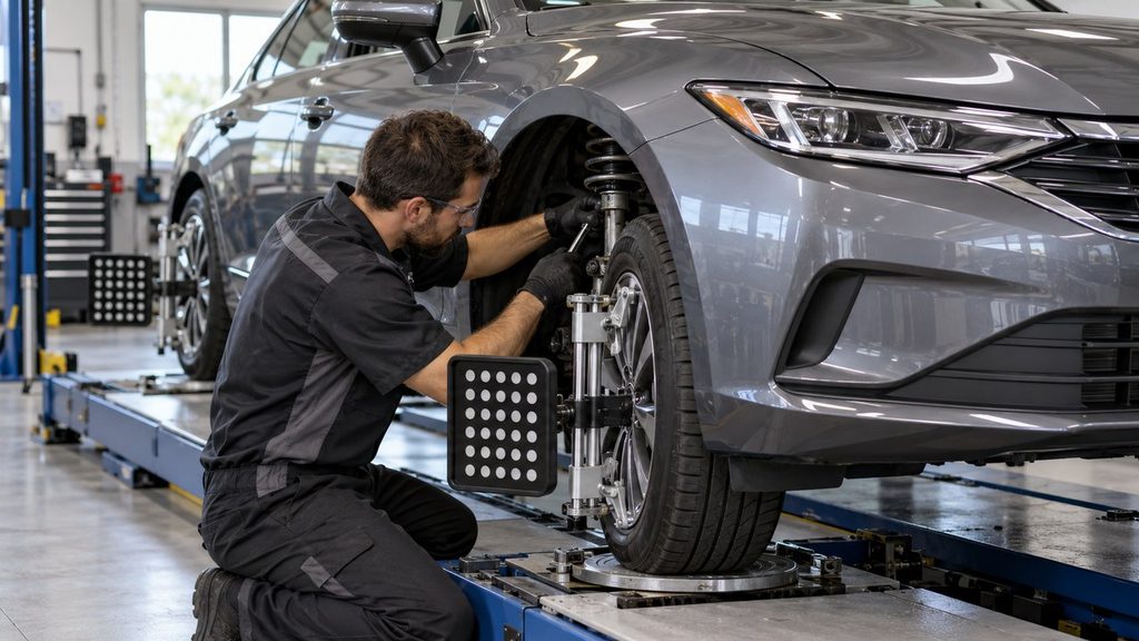
The general measuring process is:
- Position the vehicle on an appropriate level alignment surface at its specified ride height.
- Set the tire pressures and complete the required pre-alignment inspection.
- Install the alignment targets or a compatible caster/camber gauge.
- Place the front wheels on suitable turn plates and follow the equipment’s steering-sweep instructions.
- Record left and right caster and compare the results with the correct vehicle specification.
With a traditional manual gauge, one steering position establishes the reference and the opposite position provides the measurement used to determine caster. Some gauges display caster directly; others require a conversion specified by the gauge manufacturer.
Don’t apply a random multiplication factor from an online tutorial. The required calculation depends on the gauge design and steering sweep.
Can You Measure Caster With a Digital Angle Finder?
A digital inclinometer can form part of a caster-measurement setup, but it needs an appropriate wheel or hub reference and a repeatable steering-sweep procedure.
Turn plates matter because the front wheels must be able to steer without excessive tire resistance distorting the measurement. Wheel runout, floor slope, tire pressure and suspension loading can also affect the result.
For a basic comparison before and after an adjustment, suitable home alignment equipment can be useful. For a final road-vehicle alignment, a calibrated four-wheel alignment system offers a more complete picture.
How to Increase or Decrease Positive Caster
Regardless of the hardware, the underlying geometry is the same.
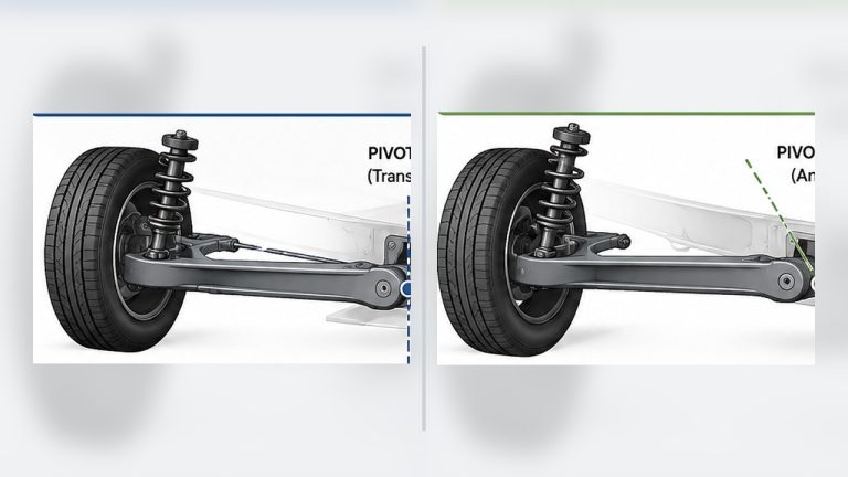
To increase positive caster: move the upper steering pivot rearward relative to the lower pivot, or move the lower pivot forward relative to the upper.
To decrease positive caster: move the upper steering pivot forward relative to the lower pivot, or move the lower pivot rearward relative to the upper.
On double-wishbone suspension, those pivots are generally the upper and lower ball joints. On a MacPherson strut, the steering axis is normally defined by the upper strut mount and lower ball joint.
That doesn’t tell you which direction to turn an eccentric bolt. Two manufacturers can position their cams differently, and moving one mounting point can also alter camber or wheelbase.
The reliable approach is to identify the approved adjustment, make a small controlled movement, then measure what actually changed.
Adjusting Caster on an IFS Truck With Eccentric Cam Bolts
Many independent-front-suspension pickups use eccentric alignment cams at the inner control-arm mounting points. These are among the most practical caster adjustment systems because the suspension provides a dedicated means of changing geometry.
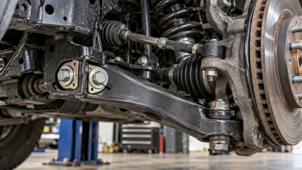
The eccentric bolt has an offset cam or washer that changes the position of the mounting point as it rotates. By controlling the front and rear positions of a control arm, the suspension can move the ball joint fore and aft.
That movement changes caster.
On some systems, coordinated movement of the eccentric cams primarily changes camber, while differential movement between the front and rear mounting points changes caster. The relationship isn’t identical on every design, which is why the vehicle-specific cam adjustment chart or procedure matters.
The Practical Adjustment Sequence
With the vehicle correctly supported according to the service manual and the alignment equipment already showing baseline readings:
- Identify the correct caster-adjustment eccentric or pair of eccentrics.
- Inspect the hardware for corrosion, loose bushings, damaged washers or previously disturbed alignment marks.
- Release only the specified adjustment fasteners using the approved procedure.
- Move the eccentric a small amount in the required direction while monitoring caster and camber.
- Secure the adjusters to the specified torque, then repeat the caster measurement.
- Correct the remaining alignment angles and verify the completed result.
Take particular care with the cam washers. They must sit correctly against their intended reaction surfaces. A bent washer, damaged bracket or seized eccentric can prevent the adjustment from holding.
If the cams reach the end of their permitted travel before caster reaches specification, don’t force them. The vehicle may need mechanical repair, a ride-height correction or an approved adjustment component with a different range.
For a real fitment example, SPC Performance lists control-arm cam-bolt kits for selected Nissan and Infiniti trucks and SUVs, including certain Frontier, Titan and Armada applications. That illustrates how an alignment kit can provide adjustment where factory hardware is limited; it does not establish compatibility with every model year or trim.
Caster Adjustment With Double-Wishbone Shims
Older cars and some performance-oriented suspensions use alignment shims at the upper control-arm shaft rather than eccentric bolts.
If the upper arm has separate front and rear mounting points, changing the shim arrangement can move its pivot shaft. That changes the position of the upper ball joint relative to the lower ball joint.
The distinction between camber and caster adjustment is important here.
Moving both upper-arm mounting points together tends to change the arm’s lateral position and therefore camber. Changing their fore-aft relationship tends to influence caster.
On a specific older cross-shaft design, that may mean adding shims at one end and removing them at the other. But the required shim movement depends on how the shaft and mounting brackets are arranged.
Never remove shims solely because another vehicle’s alignment tutorial recommends doing so. Shim thickness, minimum fastener engagement, approved stacking arrangements and tightening requirements all matter.
After changing the shim arrangement, remeasure both caster and camber. A change that corrects one angle may move the other outside its allowable range.
Can You Adjust Caster on a MacPherson-Strut Car?
Sometimes, but many MacPherson-strut cars have no ordinary factory caster adjustment.
On these vehicles, caster depends largely on the relationship between the upper strut mount and the lower ball joint. Their fore-aft positions establish the steering-axis tilt.
Possible correction methods on compatible vehicles include:
- an approved adjustable upper strut mount that permits fore-aft movement;
- a caster-capable aftermarket top plate;
- an offset strut mount designed for that chassis;
- an adjustable lower tension rod or other factory-approved locating component;
- repairing a displaced subframe or damaged suspension component.
Here’s a common source of confusion: a camber plate does not necessarily adjust caster. Many plates only allow the top of the strut to slide inward or outward, changing camber. To change caster, the design must permit the appropriate fore-aft displacement.
Similarly, loosening ordinary strut-to-knuckle mounting bolts does not automatically provide caster adjustment. Some connections allow camber correction but have little or no usable caster adjustment range.
If the manufacturer lists caster as nonadjustable and one side is significantly outside specification, inspect for damage or displacement before considering aftermarket hardware.
How to Adjust Caster on a Solid Front Axle 4×4
A solid front axle introduces a complication that independent suspensions generally don’t have: both front steering knuckles are connected to the same axle housing.
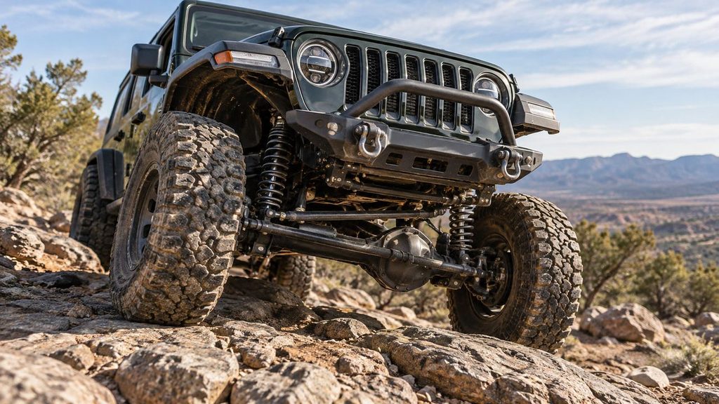
On many link-located solid-axle trucks and Jeeps, caster is changed by rotating that housing relative to the chassis. The available methods depend on the axle and suspension design.
Adjustable Upper and Lower Control Arms
On a solid axle located by upper and lower control arms, changing the effective length of the arms can rotate the axle housing.
The control-arm arrangement matters. Changing only one pair can affect axle rotation and position differently from changing both pairs together.
For example, a lifted Jeep may use longer front lower control arms or adjustable upper and lower arms to restore caster lost after the lift. But the final lengths must be chosen according to the suspension kit and vehicle geometry, not by copying another owner’s measurements.
Both sides must also be considered together. An uneven arm setup can affect axle position, bushing loading and suspension articulation.
Caster Cams and Offset Bushings
Some solid-axle trucks provide eccentric mounting bolts or application-specific bushings that allow caster correction without changing the complete control-arm assembly.
Other axle designs use offset ball-joint or steering-pivot bushings. These are not universal adjustment parts: their compatibility and effect depend on the knuckle, axle and steering-pivot arrangement.
Use the approved component instructions to determine which direction produces the required caster change. A generic eccentric bushing can alter other steering geometry or interfere with proper joint fitment if installed on the wrong application.
The Caster vs. Pinion Angle Trade-Off
This is the part many quick DIY guides leave out.
When you rotate a solid front axle housing, you change the orientation of both the steering-knuckle pivot axis and the differential pinion.
That means improving caster can move the front pinion away from its preferred driveshaft operating angle. The opposite is also possible: rotating the axle to improve the front driveshaft angle can reduce positive caster.
On a lifted four-wheel-drive vehicle, an inappropriate compromise can produce driveline vibration, excessive universal-joint operating angles or reduced steering stability.
TeraFlex discusses this caster–pinion compromise when selecting lift components for solid-front-axle Jeeps.
The correct correction depends on axle design, driveshaft configuration, suspension lift and manufacturer specifications. In substantial modifications, maintaining appropriate caster and front pinion geometry can require more than simply turning an eccentric or lengthening a control arm.
Don’t sacrifice safe steering behavior to eliminate a driveshaft vibration, and don’t ignore driveshaft geometry to obtain an arbitrary caster number. Both need to be evaluated.
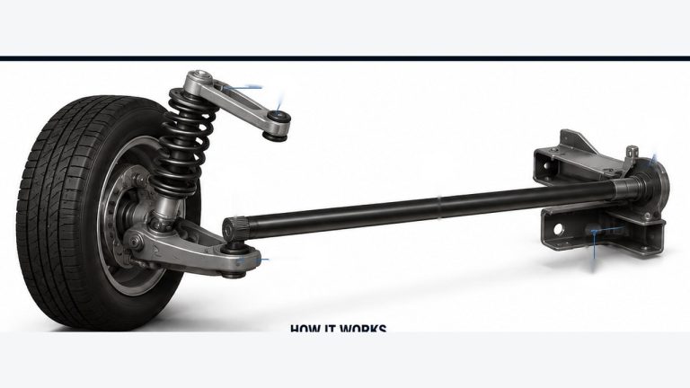
Adjustable Radius Arms and Strut Rods
Some older cars, trucks and beam-axle suspensions use radius arms or strut rods to locate suspension components longitudinally.
These components help control the forward and rearward position of the axle or lower control arm, which can influence caster.
On an application with an approved adjustable rod, changing its effective length can move the relevant lower suspension pivot and alter steering-axis inclination.
But not every radius arm or tension rod is adjustable. Some systems use fixed-length arms and specialized mounting brackets or bushings to establish the intended geometry.
Also, changing rod length can influence wheelbase, axle position and bushing preload. The correct procedure may specify a particular suspension loading condition for final tightening.
Do not use an arm’s threaded adjustment beyond its designed engagement range or substitute generic spacers to obtain more travel.
What to Do When Caster Is Out of Specification but Not Adjustable
Suppose an alignment shop measures one front wheel at a noticeably different caster angle from the other. The service manual says caster is fixed. What now?
The answer isn’t necessarily to buy a caster kit.
First, inspect the components that establish the steering-axis position. A nonadjustable caster reading can be wrong because something has moved or worn.
Potential causes include:
- a bent control arm or steering knuckle;
- incorrectly installed or worn control-arm bushings;
- a damaged or shifted subframe;
- incorrect ride height or a weak spring;
- collision or curb-impact damage;
- a distorted strut tower or chassis mounting point;
- an incorrectly fitted replacement component;
- an inaccurate alignment measurement.
Consider a car that starts pulling after hitting a curb. One caster reading is suddenly outside specification. Installing an aftermarket adjustment part might allow the alignment machine to display an acceptable value, but it wouldn’t necessarily repair a bent control arm or displaced mounting point.
Mechanical problems need to be corrected before the alignment is finalized. If a genuine correction part is appropriate, it must be approved for the vehicle and installed using its specified procedure.
Cross-Caster: Why Both Front Wheels Matter
Getting one wheel into the green range on an alignment printout isn’t the whole job.
Cross-caster, sometimes called caster split, is the difference between the left and right front caster angles.
As a general tendency, a vehicle can pull toward the side with less positive caster. But the effect interacts with cross-camber, tires, road crown and the manufacturer’s intended alignment values.
Here’s a hypothetical example:
| Position | Measured caster |
|---|---|
| Left front | +4.0° |
| Right front | +2.0° |
| Difference | 2.0° |
That would be a noticeable caster split on many road vehicles, but these are illustration-only numbers, not an alignment target. Whether either side is acceptable depends on the actual vehicle specification.
Some manufacturers deliberately specify a small left-to-right difference to help compensate for road crown. Others require both sides to stay very close together.
The correct objective is to satisfy the individual specifications and permitted cross-caster relationship—not to force identical values without checking the service data.
After Adjusting Caster, Check Camber and Toe
Caster adjustments often move the same control-arm mounting points used to influence camber. That means fixing caster can disturb a previously acceptable camber setting.
On some vehicles, camber and caster have to be adjusted together through repeated small corrections. Where separate adjustments are available, the manufacturer may specify a particular order.
If the camber also needs correction, our camber adjustment guide covers the methods used with eccentric bolts, plates and control arms.
Toe deserves special attention too. Changing control-arm position or steering-knuckle geometry can alter the relationship between the wheels and steering linkage.
Even if caster is now correct, excessive toe can create poor tracking and rapid tire scrub. For the difference between inward and outward toe settings, see our toe-in vs. toe-out comparison.
A completed alignment should verify the required caster, camber and toe values, steering-wheel position and rear thrust line as applicable. Modified solid-axle four-wheel-drive vehicles also require the relevant driveshaft and pinion-angle checks.
Can You Adjust Caster at Home?
On an adjustable suspension, an experienced home mechanic with the correct service information, tools and measuring equipment may be able to make a preliminary correction.
The difficult part isn’t necessarily turning the adjustment bolt. It’s knowing whether the new position is correct and whether the suspension is still safely assembled afterward.
A few conditions need to be met before tackling the work yourself:
- The suspension has a documented and approved adjustment mechanism.
- The steering and suspension components are free of excessive wear or structural damage.
- The vehicle can be supported and measured at the required loading condition.
- You have the correct torque values and any specified replacement fasteners.
- A suitable caster-measuring method is available.
- You can arrange a complete final alignment and, where applicable, additional steering or driveline checks.
Never loosen a loaded spring-retaining component or structural mounting connection without following the specific service procedure. Use rated supports, never rely only on a floor jack, and don’t improvise modifications to suspension brackets or steering pivots.
If the vehicle has no approved adjustment or you cannot confirm the result, a qualified alignment shop is the better option.
Questions That Come Up During Caster Adjustment
Does every car have a caster adjustment bolt?
No. Some vehicles have factory eccentric bolts, shims or adjustable control-arm mounts, while many modern MacPherson-strut vehicles have fixed caster. A correction may require an approved aftermarket component or repair of worn or damaged parts.
Can you adjust caster by turning the tie rods?
No. Tie-rod length normally adjusts toe, not caster. Caster is determined by the fore-aft orientation of the steering axis. Turning tie rods to compensate for a caster problem can create a separate toe-alignment error.
Can adjustable upper control arms correct caster on a lifted truck?
They can on compatible independent-front-suspension designs when their geometry provides the required correction. On a solid-axle vehicle, the effect depends on the entire upper and lower control-arm arrangement and how it positions or rotates the axle housing.
Will a leveling kit change caster?
It can. Raising the front ride height changes suspension operating position on many vehicles, which can alter caster and other alignment angles. The amount depends on the specific suspension, so alignment should be measured after the modification.
Should caster be adjusted before camber?
There is no universal order that applies to every alignment system. Many procedures establish caster and camber before final toe adjustment, but combined eccentric adjustments can require several passes between caster and camber. Follow the vehicle manufacturer’s procedure.
Can an alignment shop fix caster on a nonadjustable car?
An alignment shop can measure the error, inspect the suspension and determine whether an approved correction method exists. If the problem comes from a bent control arm, damaged mount or displaced subframe, that mechanical fault must be addressed rather than simply changing an adjustment number.
Before Calling the Caster Adjustment Finished
Once the correct adjustment has been made, the final test is whether the entire front suspension geometry and steering system are back within their intended operating conditions.
Make sure the caster readings meet the vehicle-specific specifications, the left-to-right difference is acceptable, and every disturbed fastener has been secured correctly. Camber and toe must also be verified, not assumed unchanged.
For solid-axle four-wheel-drive trucks, confirm that axle rotation hasn’t created an unsuitable front pinion or driveshaft operating angle. For vehicles with fixed caster, identify and repair the reason the measurement was wrong before considering the job complete.
Adjusting caster isn’t about chasing the largest positive number. It’s about putting the steering axis where that particular car or truck was designed to have it—and confirming the rest of the suspension still works correctly.