How to Replace Ball Joints: Tools, Steps & Common Mistakes
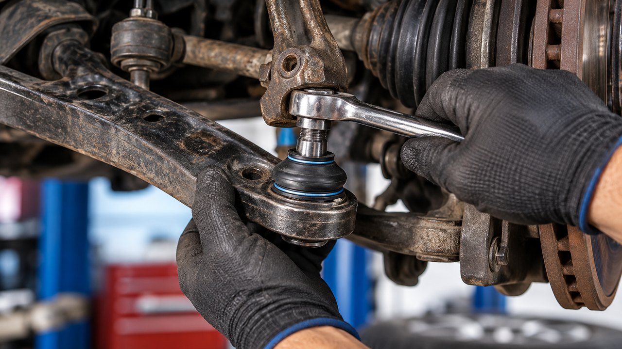
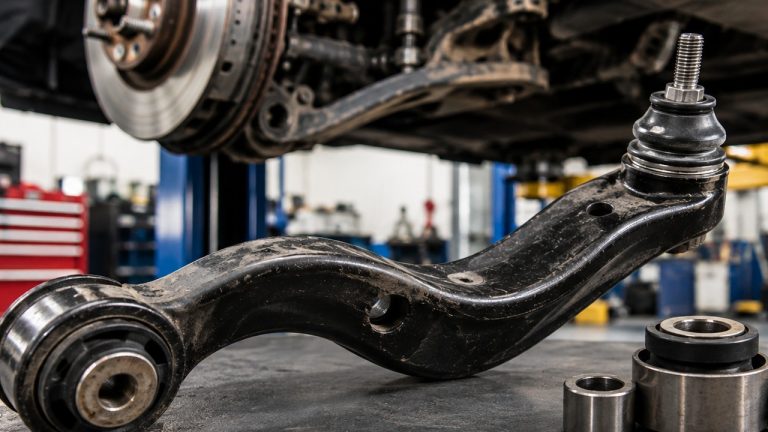
To replace ball joints, you need to separate the ball joint stud from the steering knuckle, remove the old joint from its mounting point, install the replacement, and reassemble everything with the correct fasteners and torque specifications. The removal method depends on whether your vehicle has a pressed-in, bolt-on, riveted, or integrated ball joint.
A bolt-on ball joint can sometimes be replaced with ordinary hand tools and a suitable separator. A press-fit joint generally needs a ball joint press and correctly sized adapters. If the joint is permanently integrated into the control arm, replacing the entire arm may be the only approved repair.
Here’s the basic sequence for a separately replaceable ball joint:
- Identify the correct replacement ball joint and its mounting style.
- Follow the vehicle-specific procedure for supporting the suspension, then raise and secure the vehicle.
- Remove the wheel and any components blocking access.
- Release the ball joint’s retaining hardware and separate its stud from the steering knuckle.
- Unbolt, press out, or otherwise remove the old joint using the specified method.
- Inspect the mounting bore and steering-knuckle connection.
- Install the new joint with the correct adapters, orientation, and retaining hardware.
- Torque all fasteners to specification, reassemble the suspension, and check wheel alignment.
Those steps sound simple enough on paper. The difficult part is knowing what you’re dealing with before loosening anything. On some suspensions, separating the wrong connection without supporting the spring load can cause a sudden and dangerous release of energy.
Important safety warning: Ball joints are safety-critical suspension components. Coil springs and torsion bars can remain heavily loaded even when a vehicle is raised. Before separating a ball joint, identify the suspension design and follow the manufacturer’s specific spring-load support and disassembly instructions. Never assume that putting the frame on jack stands has removed the load from the control arm. If you cannot establish a safe support procedure, have the repair performed by a qualified technician.
Identify Your Ball Joint Before Buying Tools
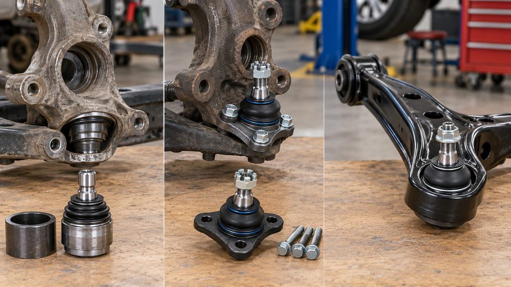
Look at the way the ball joint attaches to the control arm or steering knuckle. Two vehicles can use similar-looking joints but require completely different removal tools.
It’s also important to distinguish the ball joint’s mounting method from the way its stud attaches to the knuckle. A ball joint might be pressed into the lower control arm while its stud is secured to the steering knuckle with a castle nut. Those are two separate connections.
| Ball joint type | How it’s mounted | Typical removal approach |
|---|---|---|
| Press-in | Housing held tightly in a control arm or steering knuckle | Ball joint press with suitable receiving and installation adapters |
| Bolt-on | Joint flange secured with mounting bolts | Remove the specified fasteners after safely separating the stud |
| Riveted | Factory joint attached to the arm with permanent rivets | Remove rivets using the approved procedure; replacement may use a specified bolt kit |
| Integrated | Joint supplied as part of a complete control arm | Replace the approved assembly rather than attempting unsupported joint-only service |
| Specialty or adjustable | May use retaining sleeves, camber adjusters, or application-specific hardware | Follow the exact vehicle and part manufacturer’s instructions |
Don’t assume a universal ball joint kit covers every design. Some trucks use ball joints installed directly into the steering knuckle or axle yoke, while many passenger cars have a replaceable lower joint attached to the control arm.
A useful check is to look up the replacement part for your exact year, make, model, engine, drivetrain, and suspension package. If the parts catalog only offers a complete control arm, investigate why before ordering a standalone ball joint advertised as a universal fit.
Upper vs. Lower Ball Joints
A traditional double-wishbone suspension may have an upper and a lower ball joint at each front wheel. A MacPherson-strut suspension commonly uses a lower ball joint, with the strut assembly providing the upper steering location instead of a second conventional ball joint.
The position matters because upper and lower joints can carry different loads and require different support procedures. You cannot safely decide how to unload a joint based only on whether it’s labeled upper or lower. Spring placement, control-arm geometry, and suspension construction determine what is loaded.
For trucks with upper and lower joints, the manufacturer’s replacement procedure may specify a particular disassembly order and tightening sequence. Follow that sequence rather than replacing each joint as though it were an independent part.
Tools Needed to Replace Ball Joints
The tool list depends heavily on the vehicle. A bolt-on lower ball joint on a compact car may require substantially less equipment than pressed-in joints on a four-wheel-drive pickup.
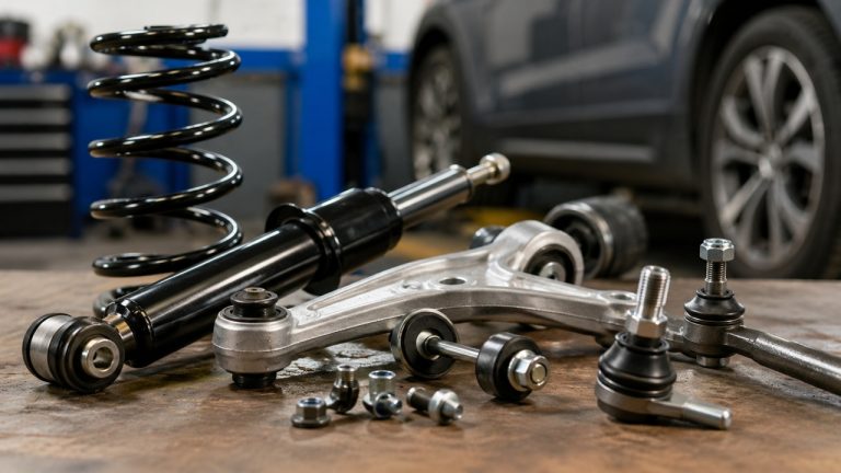
For a typical replacement, you’ll need some combination of:
- Floor jack and appropriately rated jack stands: To lift and support the vehicle at the manufacturer’s specified locations.
- Wheel chocks: To prevent unintended movement.
- Vehicle-specific suspension support equipment: Where required to control spring or torsion-bar loads.
- Socket and wrench sets: For mounting hardware, wheel fasteners, and surrounding components.
- Breaker bar: To loosen stubborn fasteners without relying on uncontrolled impacts.
- Torque wrench: Essential for tightening safety-critical fasteners to specification.
- Ball joint separator: A suitable screw-type separator is often useful for releasing a tapered stud.
- Ball joint press and adapter kit: Required for many press-fit joints.
- Snap-ring pliers: For joints secured by retaining rings.
- Needle-nose pliers: For removing old cotter pins.
- Penetrating oil and cleaning supplies: To deal with corrosion and contamination.
- Replacement hardware: New cotter pins, self-locking nuts, pinch bolts, or mounting fasteners where specified.
- Safety glasses and suitable gloves: To protect against debris and tool-related hazards.
Some repairs also require brake-caliper support hooks, an axle-nut socket, a hub or knuckle support, specialized press adapters, or equipment for removing factory rivets.
If you’re replacing a pressed-in joint, check whether a local auto parts store has a ball joint press loaner tool. The basic C-frame tool may be available, but you’ll still need to verify that its adapter set fits your particular joint and control arm.
Have the service information and replacement parts ready before taking the suspension apart. Discovering halfway through the repair that you need an unusual retaining sleeve or a single-use fastener is an unpleasant way to lose the rest of a weekend.
How to Replace Ball Joints: Step-by-Step
The following procedure explains the main operations involved in replacing a separately serviceable suspension ball joint. It’s a general workshop guide, not a substitute for model-specific instructions. The exact order and required supports vary with spring location, drivetrain, and whether the joint is fitted to the control arm, knuckle, or axle.
Step 1: Confirm the Failed Joint and Replacement Part
Start with the part you intend to replace. Verify whether the worn joint is upper or lower, left or right, and separately serviceable.
Compare the replacement with the original arrangement. Check its housing diameter, stud shape, mounting flange, retaining-ring location, and included hardware. On vehicles with adjustable or directional parts, pay attention to alignment marks and orientation requirements.
A torn dust boot isn’t automatically proof that every part of the joint has failed, but a joint with excessive play, damaged bearing surfaces, or a loose stud connection requires proper diagnosis. If the wheel has obvious movement or the joint is at risk of separation, don’t drive the vehicle while waiting for the repair.
Read the manufacturer’s service procedure now, especially the instructions for supporting the spring load, separating the stud, and positioning the steering knuckle after disconnection. Those steps determine whether the rest of the job can be performed safely.
Step 2: Raise the Vehicle and Support the Suspension Correctly
Park on a level, solid surface. Set the parking brake, chock the appropriate wheels, and loosen the wheel fasteners slightly while the tire is still on the ground.
Raise the vehicle using its approved lifting points and secure it on suitable jack stands. Make sure the vehicle is stable before removing the wheel.
Next comes the part that differs most between suspension designs: supporting the control arm, steering knuckle, or other components as directed by the service manual.
On some designs, the spring load acts through a control arm that is being disconnected. On others, the spring is retained in a strut assembly or a separate structure. A jack beneath the wrong point can create additional load rather than make the connection safe to separate.
Do not remove ball joint retaining hardware until the required load-control procedure is in place. Never rely on a hydraulic jack alone to support the vehicle, and never disconnect a spring-loaded control arm simply because the wheel is off the ground.
Step 3: Remove Components Blocking Access
Remove the wheel and inspect the area around the joint. Sometimes the ball joint is immediately accessible. On other vehicles, the brake assembly, splash shield, sway bar link, or nearby brackets limit the working space.
Only disconnect components required by the repair procedure. If the brake caliper must be removed, support it independently rather than letting its weight hang from the flexible brake hose.
Watch the ABS wheel-speed sensor wiring, brake hose, and any electronic suspension connections. These can be damaged when the steering knuckle moves away from its normal position.
Four-wheel-drive trucks and front-wheel-drive vehicles may have additional complications involving the CV axle, hub assembly, or axle-shaft clearance. Don’t pull the knuckle so far outward that the axle joint or brake hose is overstretched.
Arrange a suitable support for the knuckle if it could drop or swing when the ball joint connection is released.
Step 4: Separate the Ball Joint Stud From the Steering Knuckle
Once the suspension is correctly supported, identify how the ball joint stud is retained.
Tapered stud with a castle nut: Remove and discard the old cotter pin, then release the castle nut using the specified procedure. A properly fitted ball joint separator can break the tapered connection between the stud and steering knuckle.
Tapered stud with a self-locking nut: Remove the nut as instructed and separate the taper with an appropriate tool. Self-locking nuts that are specified as single-use must be replaced.
Cylindrical stud retained by a pinch bolt: Remove the specified clamp hardware, then release the stud using the appropriate method. This design is not the same as a tapered stud retained by a castle nut. The pinch bolt may engage a groove or notch that prevents the stud from pulling out.
Use a separator that fits the actual connection. A screw-type separator applies controlled force to a tapered joint. A pickle fork may be suitable when the joint is being discarded, but it can destroy the old rubber boot and isn’t appropriate for every knuckle arrangement.
Don’t hammer directly on the ball joint stud or attempt to drive the new joint into place with repeated blows. Some steering knuckles, especially aluminum ones, can be damaged by the wrong impact technique.
If the stud refuses to separate, stop and verify that all retaining hardware has actually been removed. A hidden pinch bolt or incorrectly positioned separator is a more useful explanation to investigate than assuming the joint simply needs a harder hit.
Step 5: Remove the Old Ball Joint From Its Mounting
With the stud safely disconnected, remove the joint using the method appropriate to its housing.
For a press-in ball joint: Remove any specified snap ring or retaining hardware first. Position the ball joint press with a receiving cup large enough to accept the outgoing joint and an adapter that applies force to the correct part of its housing. Follow the manufacturer’s specified direction of removal.
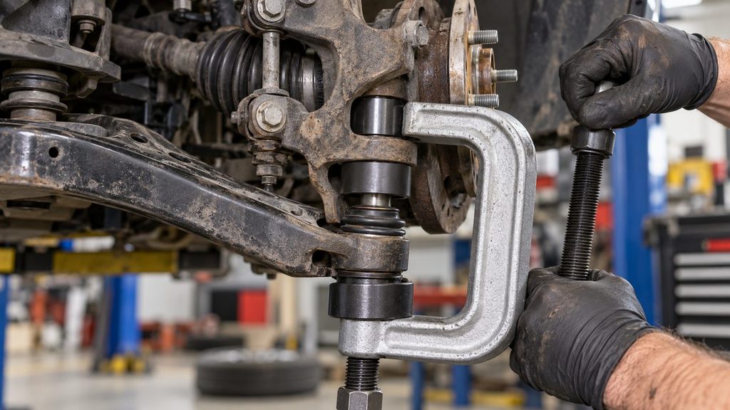
Make sure the press is aligned before applying significant force. Tighten it gradually, watching for straight movement. Stop if the control arm begins to deform, the press tilts, or the joint refuses to move despite a correctly arranged tool.
For a bolt-on ball joint: Remove the mounting bolts and carefully separate the joint flange from the arm. Note any washers, spacers, or specified fastener positions. Replacement hardware may be required even when the original bolts look undamaged.
For a riveted ball joint: Factory rivets must be removed using the approved procedure and suitable equipment. Many replacement kits secure the new joint with specially supplied bolts, but the original rivets cannot simply be replaced with arbitrary hardware-store fasteners. Rivet removal can involve cutting debris, heat, and damage risks, so this part of the job is best left to properly equipped technicians when the specified equipment isn’t available.
For an integrated ball joint: Don’t cut, grind, or press on the control arm in an attempt to create a separately serviceable joint. If the approved repair is a complete control arm assembly, replace that assembly.
Regardless of the mounting design, avoid using the control arm or steering knuckle as a surface for uncontrolled hammer blows. A damaged mounting bore can make installing the replacement impossible or unsafe.
Step 6: Inspect the Mounting Bore and Stud Connection
Don’t rush directly from removal to installation. This is your opportunity to check for damage hidden by the old joint.
On press-fit applications, inspect the bore for cracks, corrosion, raised burrs, and evidence that the old ball joint housing rotated or moved inside its mounting. The replacement depends on a secure interference fit. If the opening has been enlarged or distorted, the new joint may not be retained correctly.
Inspect the steering knuckle’s stud connection separately. A tapered stud should seat securely in its matching tapered bore without rocking. Polished wear marks, oval-shaped damage, or an obviously loose fit can indicate that the knuckle itself needs replacement.
For pinch-bolt arrangements, look for damaged clamp surfaces, corrosion, and wear around the stud’s locating feature.
Clean the surfaces as instructed by the part manufacturer. Do not enlarge a mounting bore to make the new joint easier to install, and don’t try to compensate for a loose fit with excessive tightening, improvised shims, or adhesive unless a manufacturer-approved repair specifically calls for it.
Step 7: Install the New Ball Joint
Compare the new joint with the old one before installing it. Verify that its dimensions and mounting features match the application, and check whether the manufacturer provides orientation marks or special instructions.
For a press-in joint, position the replacement squarely at the mounting bore. Arrange the installation adapters so force is applied to the appropriate outer housing or designated installation surface—not the moving ball stud, dust boot, or internal bearing assembly.
Operate the press gradually and keep the joint aligned as it enters. If it starts crooked, stop before it damages the bore. Press the joint to the specified seating position, then install the required snap ring or other retainer and verify that it is fully seated in its groove.
For a bolt-on replacement, position the flange correctly and install the specified mounting hardware. Tighten the bolts in the sequence and to the torque required for that vehicle and part.
Where a riveted factory joint has been replaced with an approved bolt-on kit, follow the kit’s fastener orientation, washer placement, and torque instructions.
If the new joint has a separate dust boot, fit it using the manufacturer’s procedure. Some boots have directional marks or a grease-relief feature that must face a particular direction. Avoid pinching the boot beneath the installation tooling.
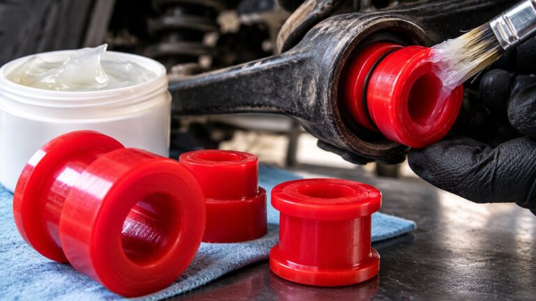
Do not coat the press-fit housing with grease or anti-seize unless the specific manufacturer instructs you to use an installation compound. A press-fit joint relies on its specified retention in the surrounding metal.
Step 8: Reconnect the Stud and Torque the Fasteners
Carefully position the steering knuckle and engage the new ball joint stud. Make sure the dust boot isn’t trapped or twisted.
On a tapered-stud design, the stud must seat properly inside the matching tapered hole. Install the correct retaining nut by hand before using a torque wrench.
Use the specified torque for your exact application. Torque values vary considerably between vehicles, upper and lower joints, steering-knuckle materials, and replacement part designs. Copying a torque figure from an unrelated truck or online video is not a safe shortcut.
If the joint uses a castle nut and cotter pin, follow the specified procedure for aligning the nut slots with the hole in the stud. Where the instructions call for advancing the nut to the next slot, tighten it further as directed—never loosen a correctly torqued castle nut merely to align the cotter-pin hole. Fit a new cotter pin and secure it properly.
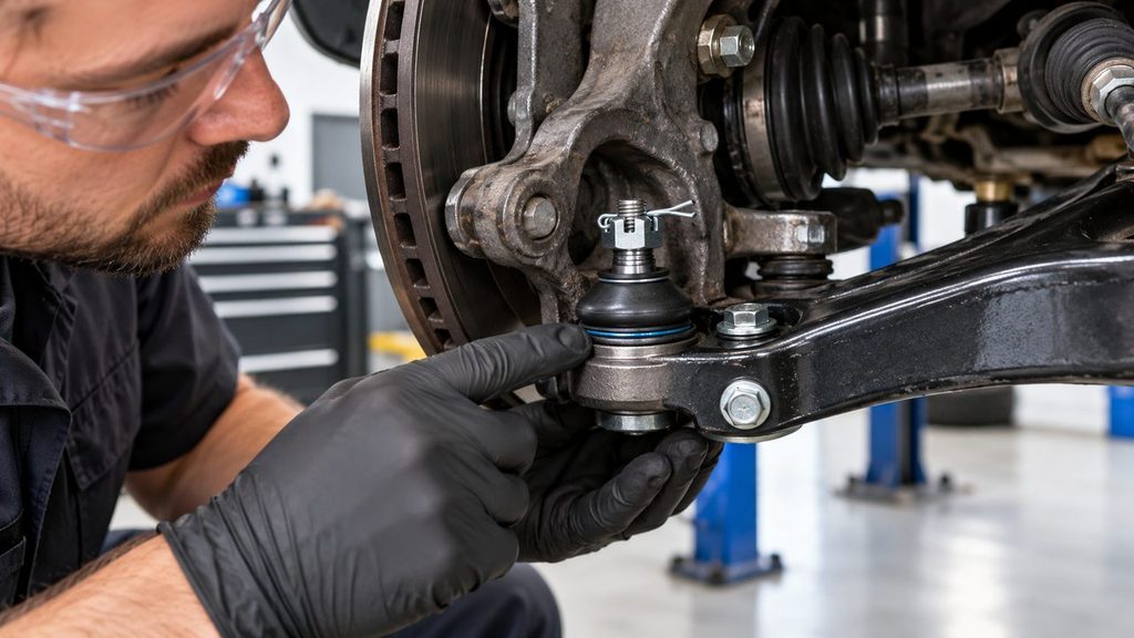
For a self-locking nut, use a new one when required. Some replacement ball joints use special tightening sequences, so check the supplied installation sheet rather than assuming every nut follows the same procedure.
With a pinch-bolt connection, verify that the stud is inserted to the correct depth and that the retaining bolt can pass through its intended position. Don’t force a pinch bolt past an improperly seated stud.
If the stud spins instead of allowing the nut to tighten, consult the part-specific method for holding or seating it. Some studs have an internal hex or other holding feature. Excessive impact-gun use is not a substitute for the correct torque procedure.
Step 9: Reassemble, Check the Joint, and Finish the Repair
Reinstall the components removed for access, following their specified assembly order. Make sure the steering knuckle, brake components, ABS wiring, and axle assembly are correctly positioned and supported.
Any control-arm bushing pivots disturbed during the repair must be tightened at the suspension position required by the manufacturer. Many bonded-rubber bushings require final tightening at normal ride height to avoid unwanted rubber preload.
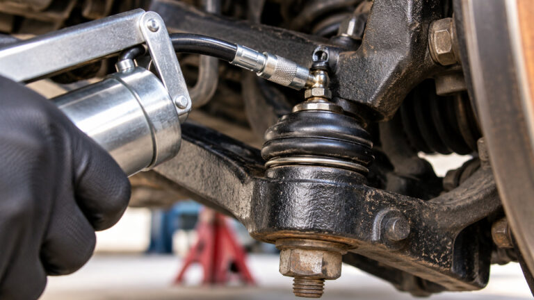
If the new ball joint is a greaseable design, install its grease fitting and lubricate it according to the replacement manufacturer’s instructions. A sealed joint with no approved grease port should not be drilled or punctured. Our guide to greasing ball joints covers the correct procedure for serviceable joints and how to avoid damaging the dust boot.
Reinstall the wheel, lower the vehicle according to the approved procedure, and torque the wheel fasteners to the specified value and pattern.
Before driving, check that all retaining hardware is present, the dust boot is secure, the steering moves through its intended range without binding, and no hose, wire, axle component, or suspension part is being pulled out of position. Verify the repair with the inspection procedure specified for the vehicle.
A wheel alignment check is recommended after ball joint replacement, particularly if control-arm mounts or adjustable suspension connections were disturbed. Our guide to alignment after replacing suspension parts explains when adjustment is likely to be necessary and why a measurement matters even when the steering wheel initially looks straight.
How to Replace Ball Joints Without a Hydraulic Press
You may not need a hydraulic shop press, but that doesn’t mean every ball joint can be replaced without any pressing equipment.
A bolt-on joint can often be removed after the fasteners and stud connection are released. A replacement joint supplied as part of a complete control arm may also eliminate the need to press the joint itself, although the arm installation still requires the correct tools and suspension support procedure.
For many pressed-in joints, a screw-operated C-frame ball joint press provides enough controlled force to remove and install the joint without a large hydraulic press. The C-frame is still a press; it simply operates mechanically.
The receiving cup must provide a clear path for the old joint to exit, and the pushing adapter must bear against the correct housing surface. The tool must also be aligned so it does not distort the arm or knuckle.
Not every press-fit ball joint is compatible with a universal C-frame. Some require vehicle-specific adapters, a special fixture, or a workshop press to complete the repair without damaging the surrounding components.
If the joint is heavily seized, or if the control arm is made of aluminum and has delicate mounting surfaces, professional pressing may be the more sensible option. A bent arm or damaged mounting bore can cost far more than having a shop handle the extraction.
Common Problems When Removing or Installing Ball Joints
One awkward fastener can turn an otherwise manageable ball joint replacement into a long afternoon. The important thing is to distinguish between a joint that’s difficult to remove and a tool arrangement that’s applying force incorrectly.
These are some of the problems worth checking before using additional force.
| Problem | Likely issue | What to check |
|---|---|---|
| Ball joint stud spins with the nut | Taper not seated or stud needs a holding tool | Stud holding feature and manufacturer-approved seating procedure |
| Tapered stud won’t separate from knuckle | Corrosion, unsuitable separator, or remaining hardware | Correct separator, support, and retaining features |
| Press-in joint won’t move | Retaining ring still installed, wrong direction, or seizure | Removal direction, cup clearance, press alignment, and joint retention |
| New joint starts crooked | Misaligned press or incorrect adapter | Stop and reset the tooling before damaging the mounting bore |
| Pinch bolt won’t slide into place | Stud not fully seated or incorrectly positioned | Stud depth, locating groove, and correct bolt |
| New joint feels loose in its mounting | Damaged or enlarged bore, or incorrect part | Housing condition and interference-fit requirements |
| Castle nut slot won’t align with cotter-pin hole | Incomplete seating, wrong hardware, or normal slot position | Specified torque and manufacturer-approved alignment method |
| Steering binds after installation | Incorrect assembly, interference, or application-specific preload issue | Stop; check orientation, clearances, and required torque sequence |
What If the Ball Joint Nut Keeps Spinning?
This usually means the stud is rotating along with the nut instead of remaining seated or held in position.
Some ball joint studs have an internal hex socket or another feature designed to hold them while the nut is turned. Other designs rely on the taper being properly seated before final tightening. Certain replacement parts have their own specified methods for engaging that taper.
Use the approach documented for the installed joint. Don’t damage the stud threads with gripping pliers, improvise unsafe loading with a jack, or rely on an impact wrench to compensate for an installation that hasn’t seated correctly.
What If a Press-In Ball Joint Is Completely Stuck?
First make sure you’ve removed the snap ring and any other retention hardware. Then verify that the receiving cup is large enough for the joint housing to pass through and that the press is pushing in the specified direction.
Check for corrosion around the housing, but remember that penetrating oil will not overcome an incorrectly positioned cup or a mechanical obstruction.
If the press frame starts twisting, an adapter bends, or the surrounding metal begins to deform, stop. More leverage won’t correct an unsuitable setup. The next step may be different adapters, removal of the arm for bench work, or professional equipment.
Should You Replace the Ball Joint or the Entire Control Arm?
Sometimes the ball joint is the only worn component, and replacing it separately is straightforward. Other times, repairing the old control arm is more trouble than it’s worth.
Consider the condition of the complete assembly. A control arm with cracked bushings, severe corrosion, structural damage, or a worn press-fit bore may no longer be a good candidate for joint-only replacement.
A replacement control arm supplied with bushings and a ball joint already installed can eliminate the pressing operation. It may also make sense when the extra labor needed to remove a seized joint eliminates most of the savings from buying the joint alone.
That doesn’t make complete arm replacement the automatic answer. A sound control arm with a properly serviceable ball joint can often remain in use after a correct repair.
Compare the complete repair scope rather than just the price of the replacement joint. Our ball joint replacement cost guide covers typical parts and labor expenses, while the lower control arm replacement cost guide explains what changes when the entire assembly is replaced.
How Long Does It Take to Replace Ball Joints?
A relatively straightforward ball joint replacement may take around one to three labor hours per side. Some bolt-on applications are quicker, while pressed-in joints, extensive disassembly, corrosion, and four-wheel-drive hardware can take considerably longer.
For a home mechanic, the first attempt often takes longer than the published labor time. Access to a lift, suitable press adapters, and experience with the vehicle can make a substantial difference.
Don’t plan the repair around the assumption that both sides will come apart equally easily. One joint may release with a normal separator while the other has a seized stud, damaged snap ring, or stubborn mounting bolts.
Also allow for the final inspection and alignment check. A replacement isn’t finished just because the new joint is bolted or pressed into place.
Mistakes That Can Ruin a New Ball Joint
A new ball joint can be damaged before the vehicle ever leaves the garage. The most serious mistakes tend to happen during pressing, stud installation, and final tightening.
- Separating a loaded suspension connection without proper support: Spring or torsion-bar energy can cause serious injury.
- Pressing on the ball stud instead of the specified housing surface: Internal bearing damage or deformation may result.
- Forgetting a snap ring: A required retaining ring must be installed and properly seated.
- Ignoring a damaged tapered bore: A new stud cannot safely compensate for a worn steering knuckle connection.
- Installing a joint crookedly: The housing or mounting bore can be distorted.
- Using the wrong fasteners: Substituting generic bolts, reusing single-use nuts, or omitting a cotter pin can compromise retention.
- Guessing torque values: Stud nuts, pinch bolts, mounting bolts, and wheel fasteners each have application-specific requirements.
- Backing off a castle nut for cotter-pin alignment: Follow the specified tightening procedure rather than loosening a correctly torqued connection.
- Damaging the dust boot: A torn boot can allow dirt and water into the new joint.
- Overgreasing the joint: Excessive grease pressure can damage certain dust boots.
- Skipping final clearance checks: Steering and suspension parts must move through their intended range without binding or contacting other components.
Perhaps the easiest mistake to underestimate is a joint that seems to fit but isn’t properly retained. If a new press-in joint slides into its housing with unexpectedly little resistance, investigate the fit. Don’t assume the retaining ring alone will make a damaged bore safe.
Frequently Asked Questions
Can you replace ball joints yourself?
Yes, on some vehicles, provided you have the correct equipment, service instructions, and experience working with suspension components. Bolt-on joints can be more approachable than heavily seized press-fit joints. Repairs involving loaded springs, complex axle arrangements, or damaged mounting points are better handled by a qualified technician if you don’t have the required tools and knowledge.
Can you replace a ball joint without removing the control arm?
Sometimes. Certain bolt-on joints and press-fit designs can be serviced with the control arm still installed. Other vehicles require arm removal to provide safe access or properly support the joint during pressing. The manufacturer’s procedure determines whether in-place service is suitable.
Can you remove a ball joint without a pickle fork?
Yes. A screw-type ball joint separator is often used to release a tapered stud without a pickle fork. The correct tool depends on the shape of the joint and steering knuckle. Some designs require a dedicated separator or a different procedure entirely.
Do you have to replace both ball joints at the same time?
Not necessarily. Replacement should be based on the condition of each joint and any manufacturer requirements. It’s sensible to inspect the opposite side because both joints may have experienced similar mileage and road conditions, but one failed joint doesn’t automatically mean every other joint must be replaced.
Is replacing lower ball joints harder than replacing upper ball joints?
Not always. A lower joint may be more difficult because of its mounting position, required press equipment, or nearby drivetrain components. On another vehicle, the upper joint may require more disassembly or a special tool. Suspension design matters more than the words upper and lower.
Do new ball joints need grease before installation?
It depends on the joint. Many sealed replacement ball joints arrive prelubricated and need no additional grease. Serviceable joints with a grease fitting may require initial lubrication according to their installation instructions. Never assume all new ball joints should be filled until grease bursts from the boot.
Do you need an alignment after replacing ball joints?
An alignment check is strongly recommended after ball joint replacement, especially when the work involves the control arm, steering knuckle, or adjustable suspension mounts. The actual need for adjustment depends on the vehicle and what was disturbed during the repair.
Can I drive immediately after replacing ball joints?
Only after the repair has been fully assembled and verified, with all required retaining hardware installed, fasteners torqued correctly, and steering and suspension movement checked. If anything binds, feels loose, makes an abnormal noise, or remains uncertain, don’t drive the vehicle until the problem is resolved. Follow the manufacturer’s post-repair inspection and alignment requirements.
Get the Fit and Fasteners Right Before Calling It Finished
Replacing ball joints isn’t one identical job across every car and truck. A small bolt-on joint, a pressed-in lower ball joint, and a pair of joints mounted in a heavy-duty truck axle can require very different tools and disassembly procedures.
The common thread is simple: identify the mounting design, support the suspension correctly, remove the old joint without damaging its housing, and make sure the replacement is seated and retained exactly as specified.
Pay particular attention to the stud-to-knuckle fit, press adapters, snap rings, pinch bolts, and final torque. Those details are easy to overlook when the main goal is getting the old joint out, but they’re what determine whether the new part stays securely in place.
If the suspension design is unfamiliar, the spring load cannot be controlled safely, or a mounting point appears damaged, professional repair is the sensible choice. When the joint is separately serviceable and the correct equipment is available, though, a careful replacement can restore the connection without replacing otherwise healthy suspension components.